Category: Towers & Foundations
-
Grouting the Tower-Foundation Interface — Materials, Process, and Quality Control
The small layer that carries the full weight of a wind turbine — and why getting it wrong can be catastrophic. There is a thin layer of material between the steel tower of a wind turbine and the concrete foundation it sits on. It is typically 20 to 50 millimetres thick, it weighs less than…
-
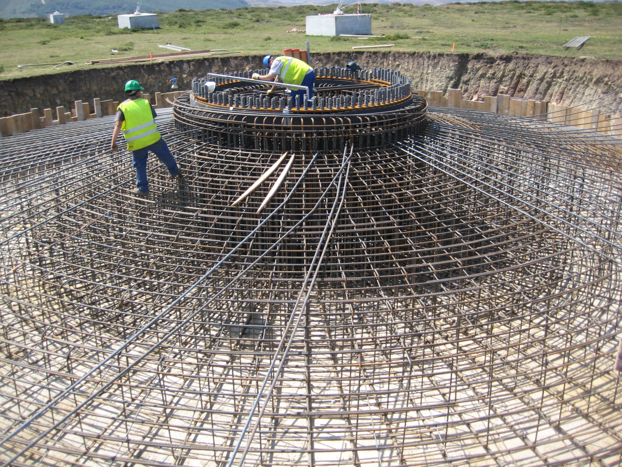
Wind Farm Foundation Repair: A Real Case Study
When a gravity foundation cracks, how do you diagnose the problem, design the fix, and execute the repair — all while the turbine stays in place? Wind turbine foundations are designed to last 25 to 30+ years, matching the operational life of the turbine. They are massive reinforced concrete structures, typically buried several metres underground,…
-
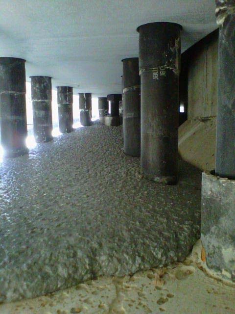
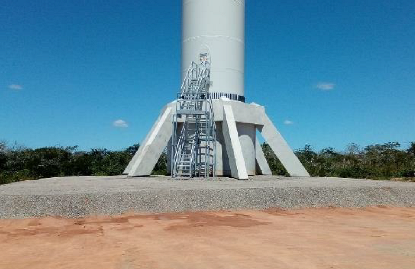
Dobberzin WF
The photos below, stolen from LinkedIn, are from one of the last tenders I worked on. It is of the Dobberzin wind farm, with the Nordex concrete tower installed. Interesting to note how the keystones are assembled and joined together by grouting.
-
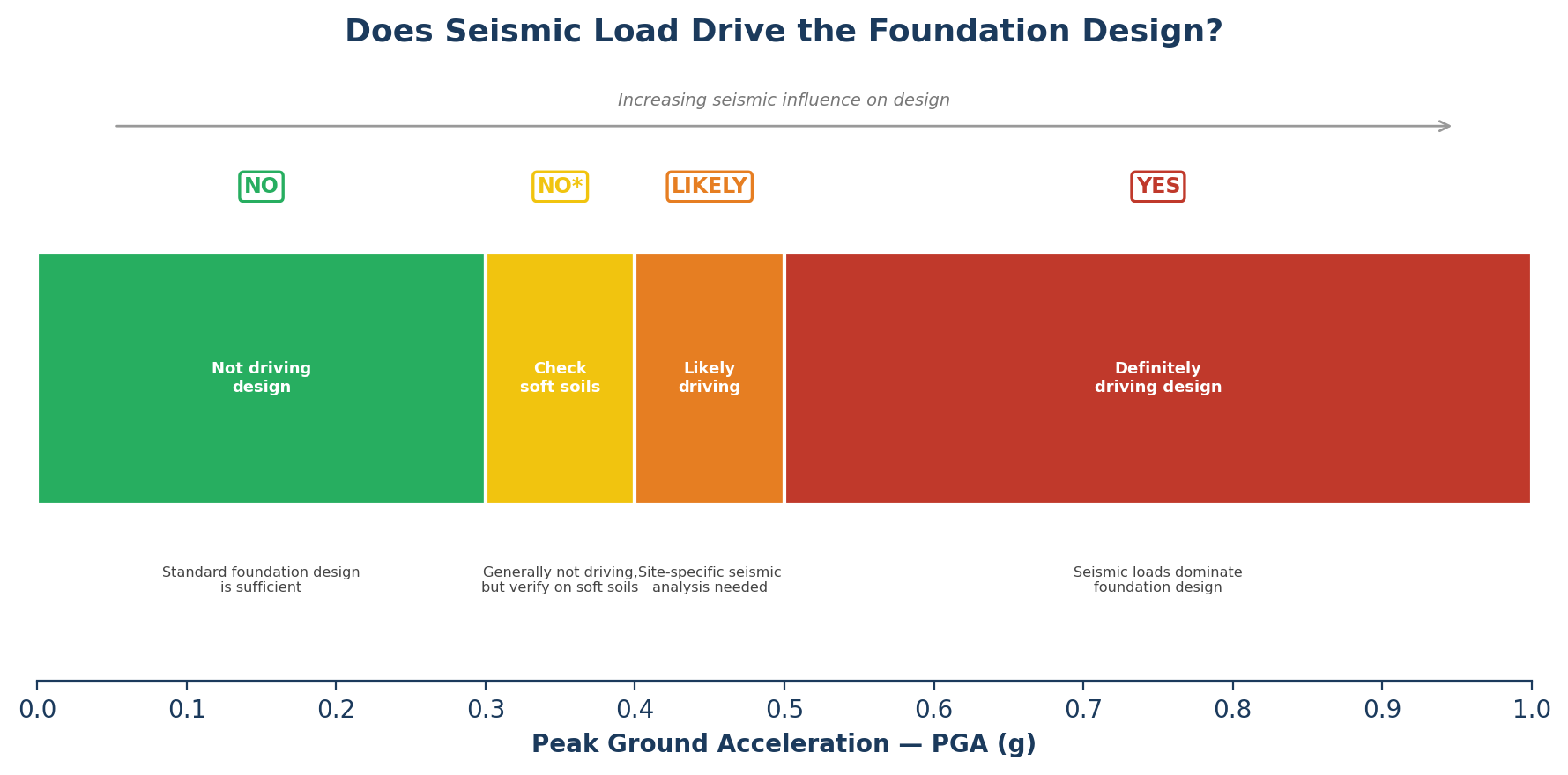
When Do Seismic Loads Actually Matter? A Practical Peak Ground Acceleration (PGA) Guide
Most wind farms never need to worry about earthquakes. Here’s how to tell when yours does — and what changes in the design when it does. Wind turbines are already designed for enormous lateral loads. A 4 MW turbine on an 80-metre tower generates overturning moments in the range of 100,000 kNm under extreme wind…
-
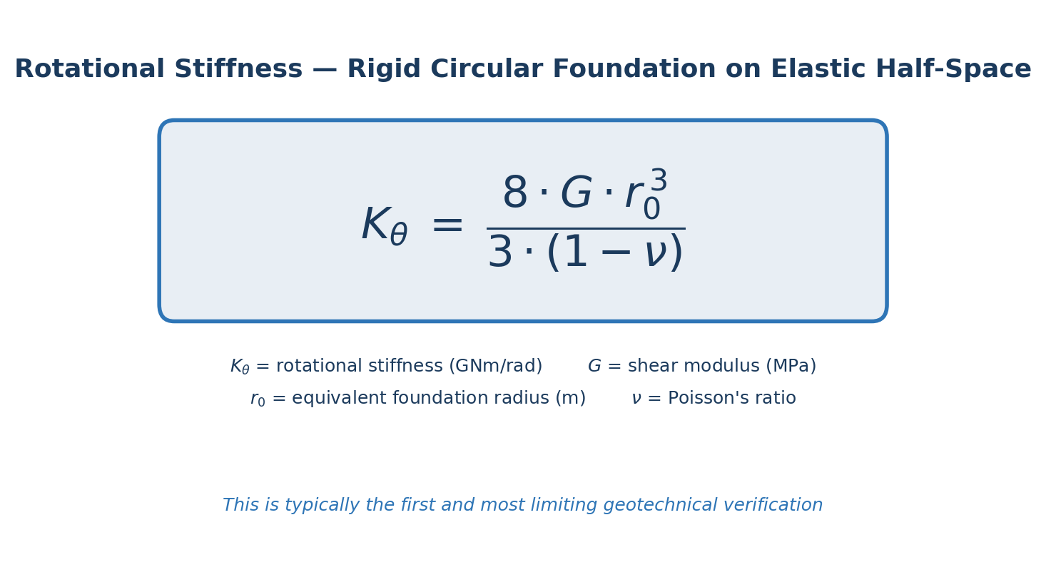
Rotational Stiffness: The Check That (Often) Drives Foundation Size
Yes, sometimes the diameter of your gravity foundation is not governed by soil bearing capacity… Sometimes, when you run all the foundation design checks (bearing capacity, sliding, overturning, settlement…) you discover that the one that actually sizes the foundation is none of the above. It is rotational stiffness. This is the check that could drive…
-
Esteyco’s braced foundation: an update
This article is an update to the post I have made some time ago on Esteyco’s Braced Foundation. I have been contacted by David Sarrasín, Product Development Director at Esteyco. He provided an interesting presentation of the braced foundation solution. He also gave me more context on the solution. This is the additional info he…
-

Nabrawind Skylift
A new article written by my friend and colleague JR Carril. JR is a civil engineer specialized in renewable energy. He helps me to keep this blog going as I can’t find the time to write new articles.Thank you JR! For those who don´t know them, Nabrawind Technologies is a Spanish company based in Pamplona,…
-
Ground Improvement for Wind Farms: 6 Techniques Compared
When shallow soil won’t cooperate, you have more options than you think — but choosing the wrong one costs time and money. Not every wind farm sits on good ground. Several of the projects I’ve worked on had some geotechnical issue that made standard gravity foundations impractical without treating the soil first. Maybe it’s loose…
-
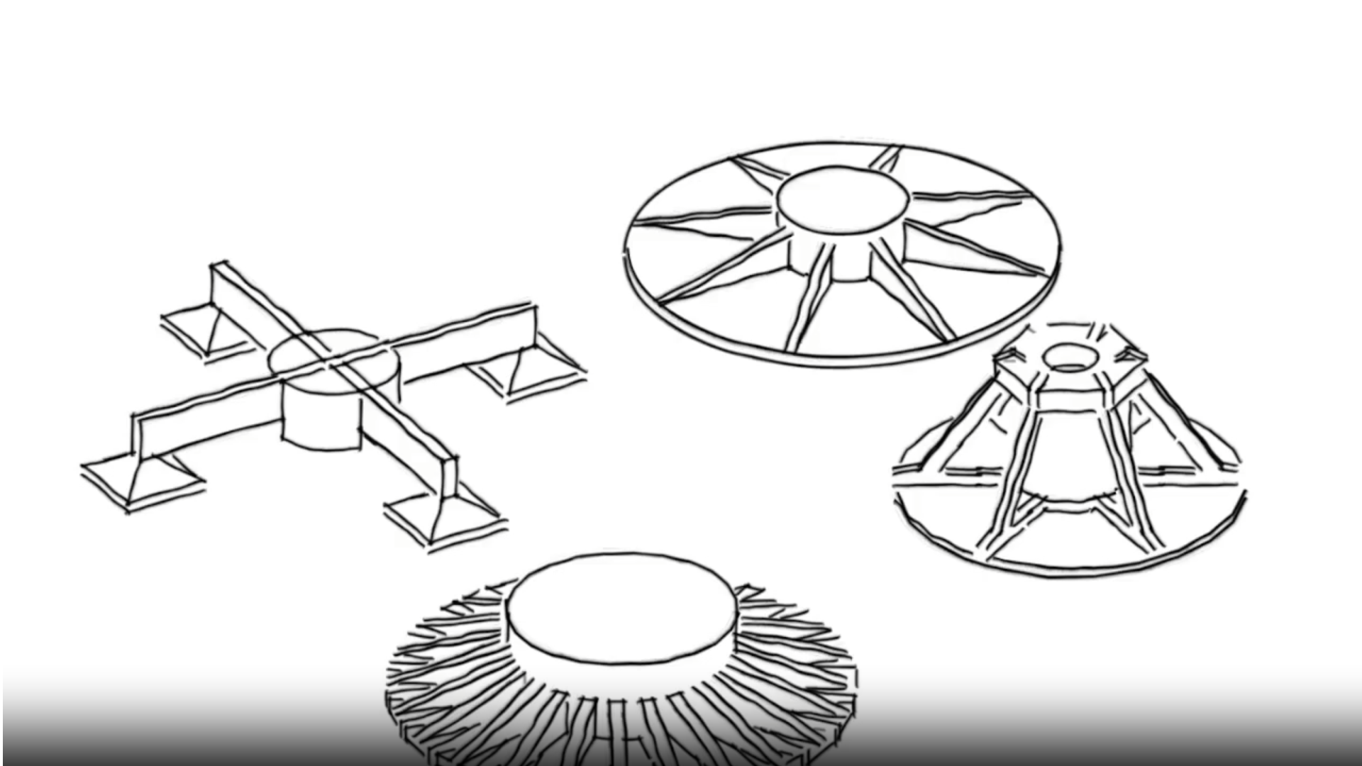
Concrete laminar wind turbine foundations: doing more with less
Concrete laminar foundation (or CLF) is a new type of wind turbine foundation developed by my friend José Carril and the team of MS-RDITECH. The CLF foundation is a new wind turbine foundation concept based on laminar elements. It is composed by 3 main elements: a lower slab, a central cylinder and a top shell….