This article is an update to the post I have made some time ago on Esteyco’s Braced Foundation.
I have been contacted by David Sarrasín, Product Development Director at Esteyco.
He provided an interesting presentation of the braced foundation solution.
He also gave me more context on the solution.
This is the additional info he provided:
Several things have happened since the designs you reported on:
We have included designs with heights over terrain level of 8m and even 10 meters, so that foundations increase the energy production gain even more.
Value of hub height increases is proportional to both the height gained and the size of the turbine… and turbines today are 5 to 7MW mainstream – even in the US they are rapidly growing in size.
As a reference, for a typical windfarm with medium characteristics, the actual value of an 8m hub height increase on a 6.x MW turbine would pay a 200k$ per wind turbine price increase while maintaining the same LCoE, and quite a lot more in good windfarm scenarios.
Considering that the foundation is not more expensive than its conventional counterpart, this is a lot of contribution to the LCoE reduction made by the foundation.
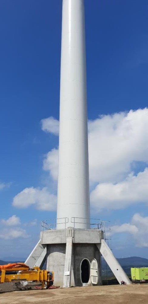
We have included the possibility to enter the turbine through the foundation, by opening a door in the central shaft (no bolts in there as they are confined to the upper slab, so we can go for up to 1m wide doors with no issues) and converting the upper slab in an upper ring, with a 2.5m to 3m hole so that even the wind turbine elevator can descend to entrance door level. We use this design if the OEM allows because he modifies tower bottom to remove door. Some times this is not possible and external ladder remains in place to reach tower entrance.
We have removed prestressing of the braces.
Achieving this was not hard at all: we increased the amount of rebar in the braces, and we also needed to increase the number of braces to eight rather than six to maintain rigidity in the parameters required by modern turbines. So now the foundation is just rebar and concrete, and same types of concrete used as in conventional foundations.
We have very much simplified the construction process.
We have done several things for this:
– We have removed the perimetral beams and the radial beams, in exchange for a bit thicker lower slab. Some extra concrete quantities, but a very simplified execution process.
– The central shaft is constructed first, before the lower slab or the braces are done. This simplifies construction a lot, because rebar placement and formwork and scaffolding handling is made with no former construction getting in the way.
– Braces are not V-shaped any more – diagonal part plus radial beam part – but they are just the diagonal brace. Construction is simpler, they are lighter – which is important because designs going +8m or +10m imply longer braces, and we don’t want to use bigger cranes. Of course, this means they are not self-stable any more, but this is not a problem, because as explained, the central ring or shaft is already constructed when the braces are placed, so the brace is laid on its legs in the base and resting on the top of the central ring at their top.
– Upper slab is now circular instead of hexagonal. This makes for an ad-hoc formwork, but it is a small formwork. On the side of the advantages, rebar is very simplified, as all radial rebar has the same length and perimetral rebar is also circular. Very important, the slab is not a slab any more but a ring, with inner diameter of up to 3m, so that access to the tower can be done through the central shaft where tower bottom equipment, ladder and elevator can be placed, so even when gaining 8m hub height, entrance to the turbine is at terrain level.
All these characteristics have improved the solution a lot.
And also, the evolution to turbines over 5MW or even 7MW with very big rotors has helped in the comparison: conventional foundations today are often over 700 cubic meters or even 900 m3 of concrete, so that the amount of concrete saving per foundation remains at 30 to 40%, but it is this saving percentage on a much bigger amount of concrete.
Some other advantages on the same line: customers tell us that today, due to this need of 700 or more m3 of concrete non-stop for foundations for big turbines, the size of the concrete plants required and the risks of issues with supply that can lead to unwanted dry joints is quite more menacing than it used to be.
Also, in certain weathers, the curing process of such big foundations poses concerns.
A lot of things improved, as you may see.
There are up to now over 330 foundations installed, but it should be more, in my opinion.
Construction process, even simplified as explained, is more complex than standard foundations if not appropriate, ad-hoc designed formwork and scaffolding is used.
Reality is that customers are deciding to use the foundation on a windfarm by windfarm basis, at a quite late moment in the windfarm development, which is not best for two reasons: first many times they find out that too much is already launched to change foundation design and hub height without risking the windfarm planning, so decision is not to use it.
Second, if decision is to use it, both scheduling and also lack of sufficient units for depreciation justify constructors not to make ad-hoc, robust, well thought out formwork and scaffolding, using commercial, universal sets that can be used but reduce efficiency, that impact total construction time.
We are optimistic because lately some customers are shifting to looking to this solution not that much as a solution for a given windfarm but rather something to include in their portfolio, for many future windfarms.
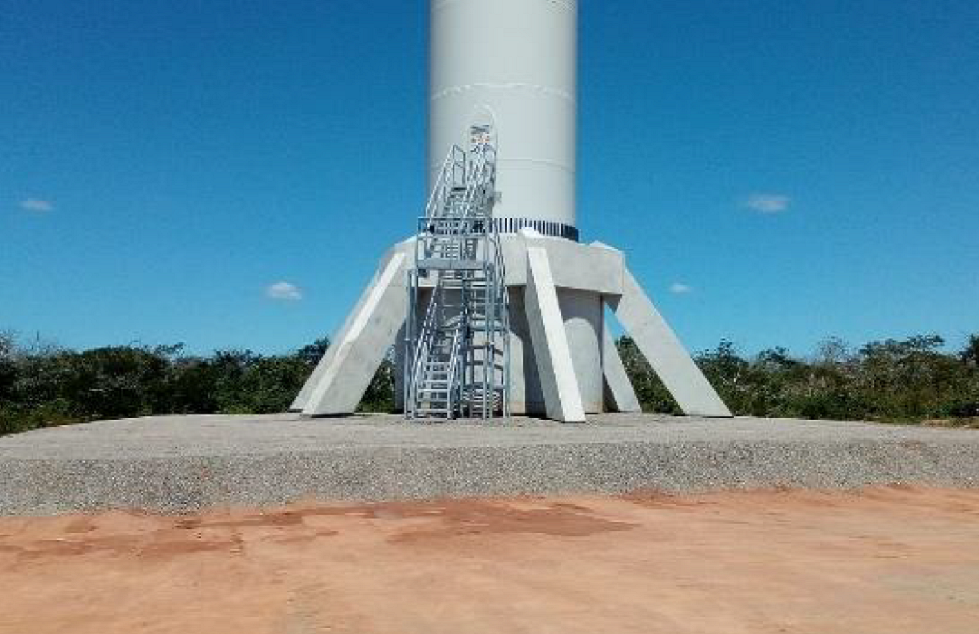
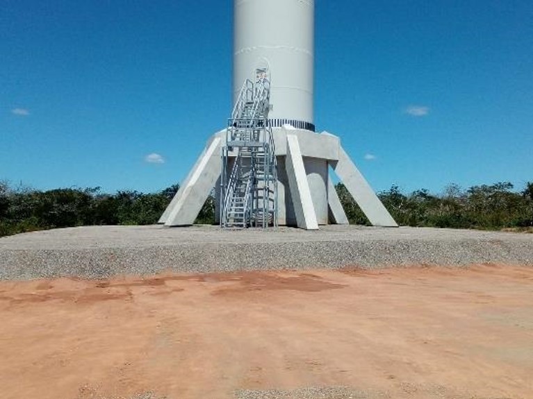
You can find some pictures of the technical solution below.
Please note that there are two alternative positions for the door (bottom of the foundation or in the tower adding a stair).
Leave a Reply