
Now Available
Wind Farm Balance of Plant
Everything in a wind farm that is not the turbine: roads, crane pads, foundations, cables, substations, and the engineering that ties them all together.
Written by a practitioner with real-world experience across dozens of projects in Europe, Latin America, and beyond.
€49.00
Instant Download
30-day money-back guarantee
What You’ll Learn
A complete overview of every BoP discipline — from soil to substation
01
Geotechnical Investigation
Soil surveys, CPT tests, lab analysis, and how they drive foundation and road design
02
Access Roads & Crane Pads
Design criteria, material selection, drainage, and the logistics of moving 80-meter blades
03
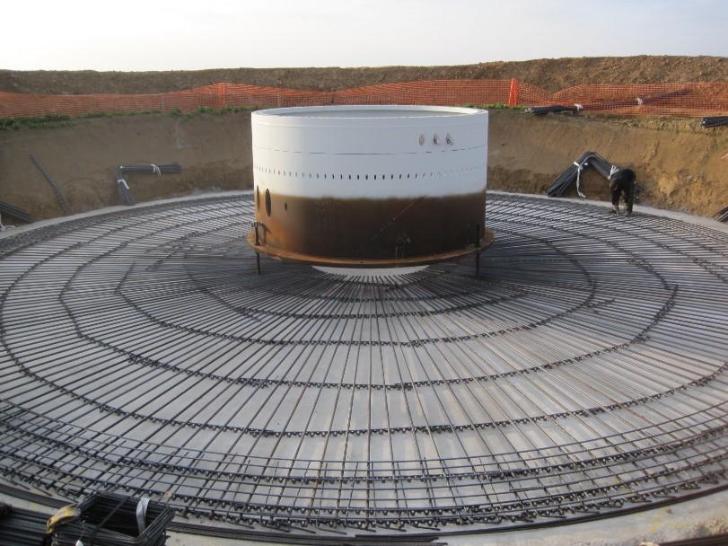
Foundations
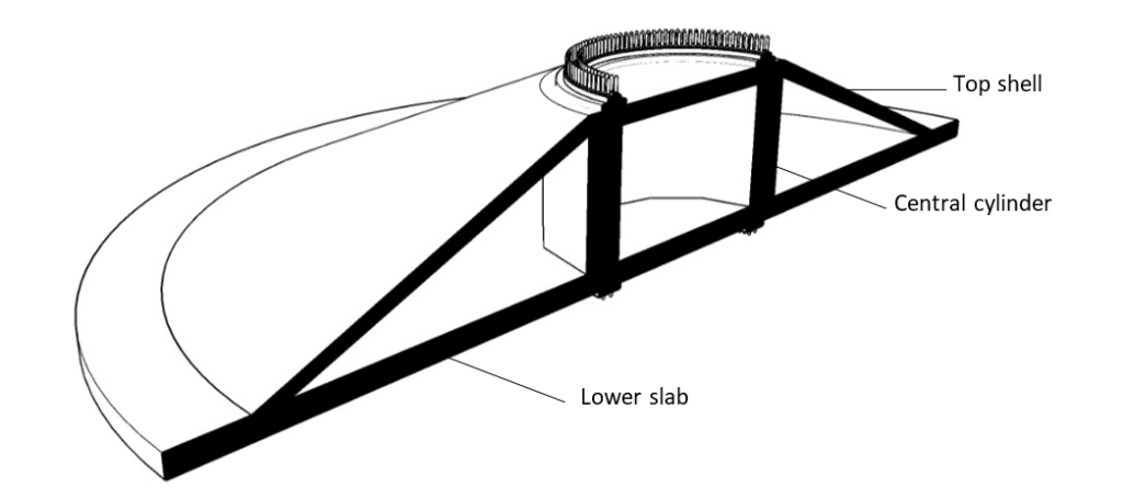
Gravity, rock-anchored, and piled foundations — design loads, concrete, and construction sequences
04
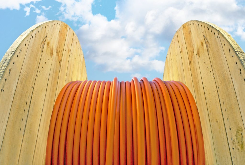
MV Cable Network
Cable sizing, trench design, route optimization, and how to minimize electrical losses
05
Substation & Grid
Transformers, switchgear, protection systems, and the connection to the national grid
06
Project Economics
Cost breakdown, BoP budget benchmarks, and how engineering decisions impact the bottom line
This is how it all started…
Many years ago, I had the opportunity to switch from the sector I was working in (infrastructure design) to renewables.
It seemed like an extremely interesting world to me, and I decided to start writing a blog to report on what I was discovering and what I found most interesting.
15+ years later the website is still up and running.
A lot has happened in the meantime – for example, three children have arrived, making it increasingly difficult to find the time to update it.
I hope you will excuse me if I am unable to write often. Of course if you feel like collaborating and sharing content you are welcome!
Happy reading, Francesco

Some articles you might find interesting


-
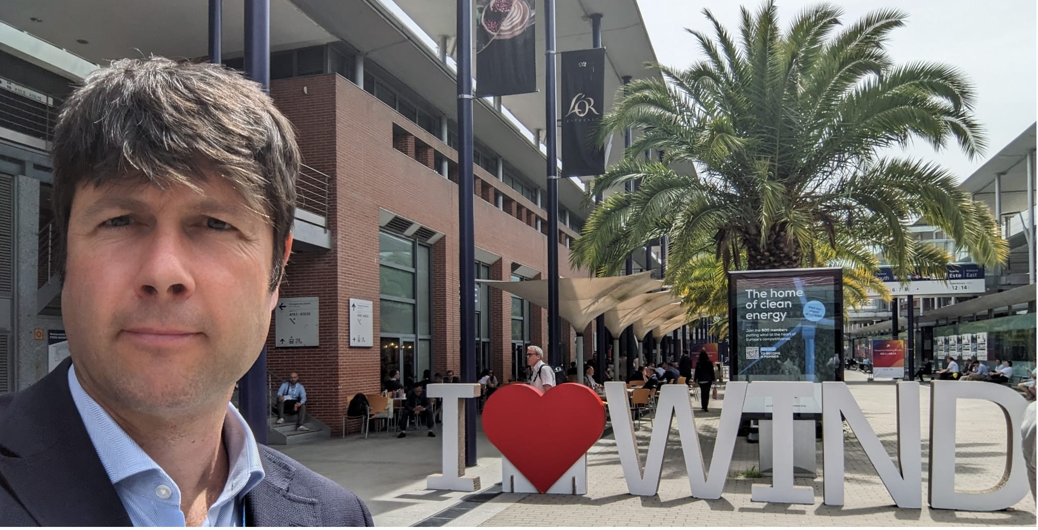
WindEurope Madrid 2026
CONTINUE READING: WindEurope Madrid 2026Last week I had the chance to travel to Madrid for windeurope, where I had the pleasure of reconnecting with many friends, colleagues, and former coworkers. People with whom I’ve shared projects, challenges, and long days (and nights) on wind farms across different countries. Among others I met Jesus, now at OceanWinds, Alessio and Ignacio,…
-
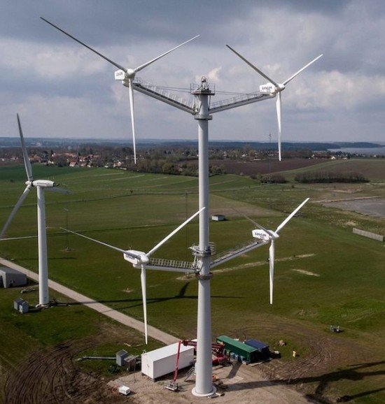
The interface problem: scope gaps in wind farm construction
CONTINUE READING: The interface problem: scope gaps in wind farm constructionIf you decide to divide the work on building your wind farm among several companies, you will likely save money. However, the trade-off will be coordination issues. This is the problem that shows up when two subcontractors are standing next to a half-finished cable trench, each one explaining why the other should complete the work….
-
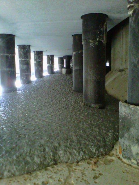
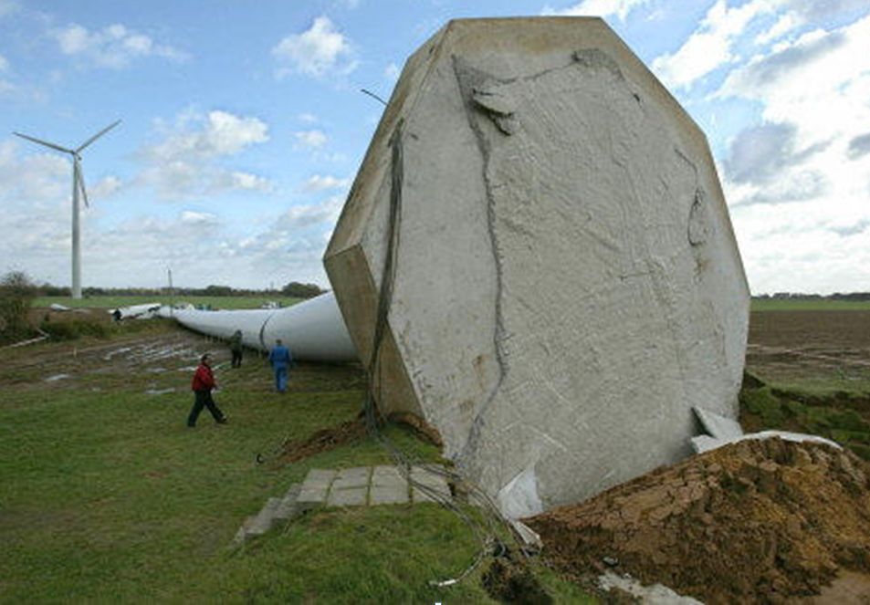
Grouting the Tower-Foundation Interface — Materials, Process, and Quality Control
CONTINUE READING: Grouting the Tower-Foundation Interface — Materials, Process, and Quality ControlThe small layer that carries the full weight of a wind turbine — and why getting it wrong can be catastrophic. There is a thin layer of material between the steel tower of a wind turbine and the concrete foundation it sits on. It is typically 20 to 50 millimetres thick, it weighs less than…