The use of cable stayed wind turbine towers is somehow unusual.
They are however relevant when very high steel towers are used (from 100+ meters to the current record, 175m).
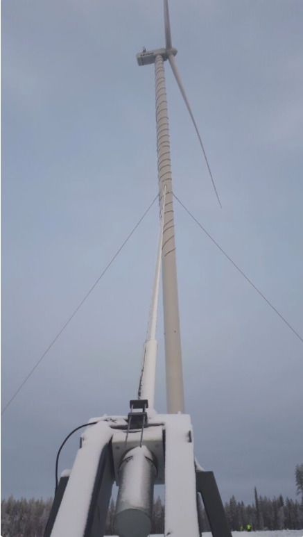
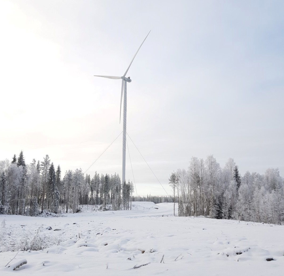
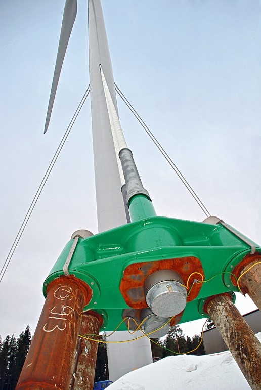
An example can be seen in the picture below.
They have been taken by Peikko, a Finnish company in charge of the design and construction of the wind turbines’ foundations.
The engineers at Peikko are very experienced and they have developed several interesting projects (see for instance their rock anchor solution).
They are also very nice and easy to work with (and if you wonder what is the logo of the company, a Peikko is a mythical creature, similar to a troll).
The way a cable stayed structure work is similar to a beam with a certain number of intermediate supports. This shortens the span of each element.
The pictures below are taken from a book on bridges from Javier Manterola, one of my favourite structural engineers.
The first is a cable stayed bridge:
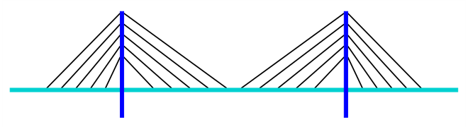
The same concept is applicable to a suspension bridge:
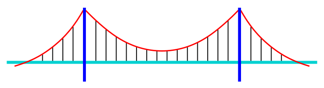
The main difference between both concepts is that the suspension bridge requires a heavy overhanging cable (in red in the image).
This cable “collects” the vertical forces from the suspension cables.
By doing so a suspension bridge avoids the horizontal forces – one of the main problems of the cable stayed structures.
In the case of bridges we are supporting the structure from the top with tensioned cables – a very efficient solution.
In the case of wind turbines towers we are supporting a structure from the bottom.
The main force acting over a wind turbine is a massive bending moment, created by the horizontal loads of the wind on the blades.
The tower is behaving as a vertical cantilever fixed at the foundation.
Using cables we are creating a fixity point in the middle of the tower. This reduce the bending moment at the bottom.
The structural scheme would be as follows (“before” the cables on the left and “after” the cables in the right):
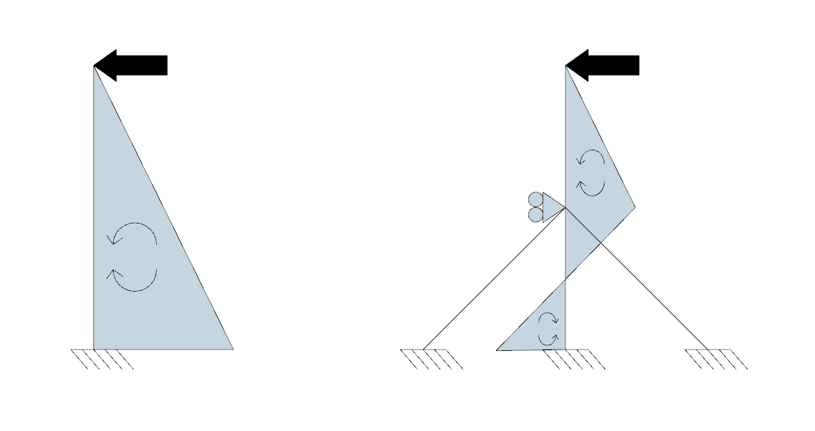
The fixity point created in the tower by the cables reduces significantly the bending moments on the tower.
This allows using smaller diameters for the towers, with strong savings in material and transport costs.
It also makes possible using towers with very high hub heights.
However, there are not only advantages.
Some problems with this solution are:
- Additional foundations for the cables are needed. These satellite foundation for the cables are taking horizontal and vertical (upwards) loads, complicating its design.
- An interface element is required to anchor the cable in the tower.
- Cables need to be pre-stressed – this could create delays the installation.
- The topography in the area needs to be flat to avoid stiffness differences between the cables (this could happen is they have very different lengths).
- Aerolastic phenomena in the cables need to be considered in the design.
Interestingly, in this project both cable stayed towers and helical strakes are used.

Another company who has worked at this concept is Mervento (curiously, another Finnish company).
Leave a Reply