Since some years ago almost all wind turbine manufacturers (“OEM” – I hate acronyms) have modified their tower to foundation interface.
The previous technical solution to connect tower and foundation was based on an embedded steel section (like a “ring” inside the foundation).
It did not work properly and the issues caused by this element might be easily subject of several articles, about the problems caused by the ring and on the solutions developed to fix those problems (i.e. retrofitting and repairs works necessary to ensure the necessary lifetime of the turbine foundations).
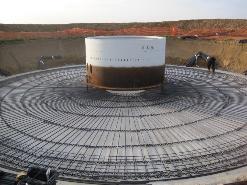
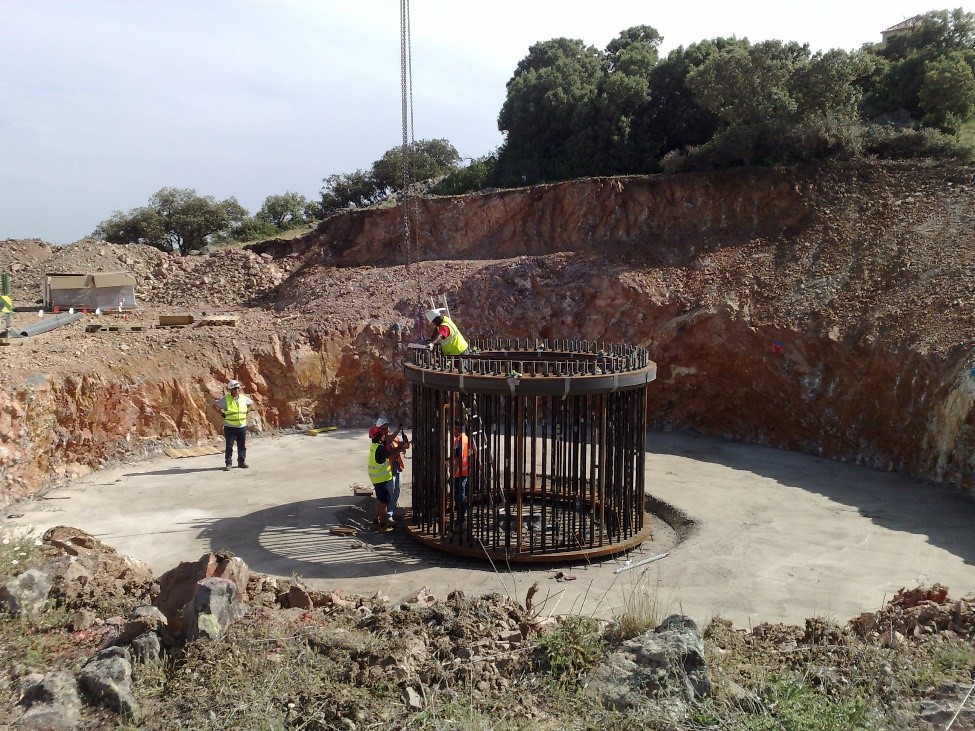
In the last years (I would say since around 2010) the embedded ring has been replaced with a pre-stressed anchor cage, as shown in the following picture:
The design methodology for this element is usually based on simplified hypothesis:
The first assumption is that the tensile/compression strength on each element is calculated assuming a uniform load distribution, usually using formulas such as:
T = 4Md / (n*D) + N/n
Being
T = Maximum tension force on the more loaded bolt
Md = Bending moment from the tower
n = Number of anchors
D = Average diameter of the anchor cage
N = Axial force
This is usually known as the “Petersen approach”.
Petersen is a German engineer who wrote a book about steel structure design appropriately titled “Stahlbau” (“steel construction” in German) where this calculation method is presented.
The second assumption is that the tensile force is distributed between concrete and steel if there is no decompression.
If decompression happens (something that will always happen under ultimate limit state factored loads) all the tensile force will be taken by the steel.
The only problem with this approach is that the first assumption is only true in case there is no decompression.
This approach leads to conservative results, as it does not account for the force re-distribution due to the stiffness change when decompression occurs.
However, it is very easy to obtain the maximum tension the more loaded bolt or to calculate the needed number bolts or their dimensions for a given tension.
When decompression occurs the stiffness in the “compressed” side and in the “tensioned” side stops having the same value, as the concrete stops providing its stiffness (this is the magic of pre-stressing, before de-compression the concrete is somehow taking some tension, a thing that concrete rarely does).
In the compressed side we will have an area of concrete under compression and bolts in tension (due to the prestressing), that take the compression by de-tensioning.
In the tensioned side we will only have the bolts in tension.
Similarly to a hyper static structure the stiffer side (in this case the one under compression) is able to take more load.
This works like a beam supported by springs:
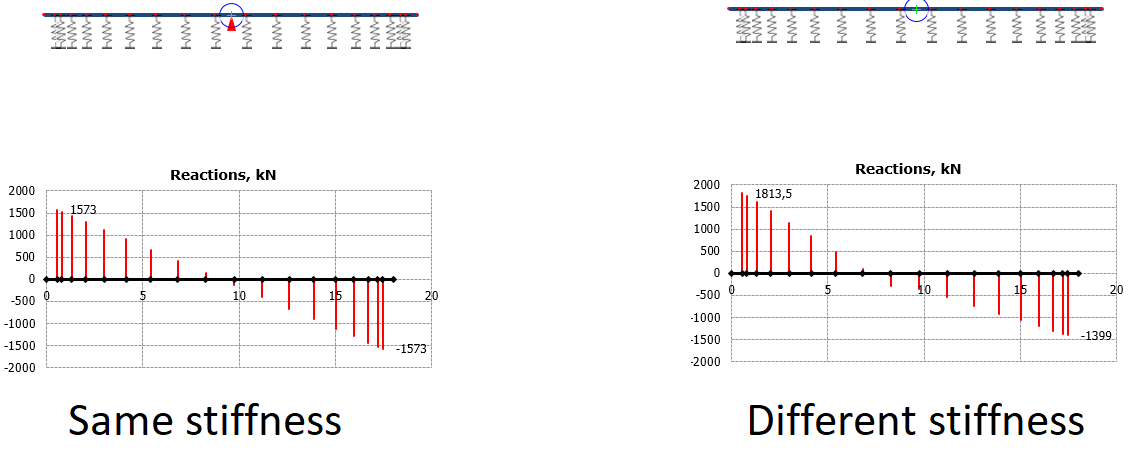
In the picture on the left all the springs have the same stiffness. This would be the current design model, as in the formula shown above.
In the picture on the right the tension springs (right side of the beam) have only half the stiffness.
This is just to show how stiffness affects the force distribution, in a real anchor cage the loss of stiffness when decompression occurs might be over 80% as the concrete area contribution it is much bigger than the bolts area (total stiffness would be Es*As+Ec*Ac, being Es and As the area and elastic modulus of steel, and Ec, Ac the ones from concrete).
The “softer springs” on the right take less load, that is redistributed to the more rigid area on the left.
Please note that this would not happen in an isostatic structure (with only two supports)
As the neutral axis moves, the redistribution of forces changes. This lead to a non-linear calculation.
To perform this analysis we can implement a model with a homogenized concrete-steel section, and with variable parameters depending of the location of the neutral axis. Using this type model, we would be able to obtain the maximum stress on concrete and the tensile force on the pre-stressing element.
This way the anchors size may be adjusted, and we will get a more accurate value for the concrete compression which is slightly underestimated with the current models.
I am not going more deep into this boring details about calculations but I think that it is interesting to know that there is still room for optimization in anchor cage design.
Leave a Reply