Category: Cranes and special transport
-
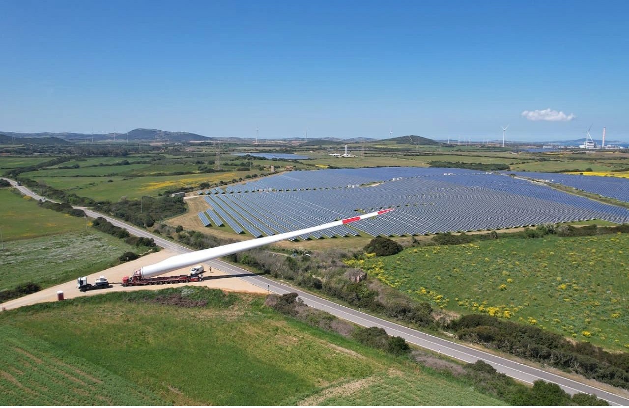
Blade lifter in action
I stole these photos from Henry Del Fabbro, who is not only a good friend but also an experienced Tender Manager and Project Manager.This is an example of a project in which a blade lifter was used.The model in question was produced by Goldhofer, a german company developing cool transport solutions (check their page). They…
-
Tower cranes: a real alternative to lattice boom cranes?
The constant search for higher rated power, taller towers and longer blades has pushed wind turbine manufacturers in an arms race to secure a position in an extremely competitive market. Today in the onshore market there are machines with rated power close to 6MW, hub heights in a range of 150-165m and blades longer than…
-
Blade mover – a flexible dual transport system
One of the many problems posed by the huge wind turbine blades currently in the market is how to move them quickly and safely. In some situations (like in the factories, or when blades are temporarily stored before installation) space can be extremely limited and there is the risk of damages. Additionally manipulating and moving…
-
Blades installation: more options than you might think
How are the blades of the wind turbines installed? Although in general each wind turbine model has only one installation procedure, several technical alternatives have been developed through the years. The quicker and easier method is probably to assembly the rotor on the ground. The three blades are connected to the hub and then lifted…
-
Liebherr crane configuration codes: what do they actually mean?
Have you ever wondered what is the logic behind the crane configuration codes used by Liebherr? How could an unintelligible code such as “SL13DFB” being interpreted? There is a logic behind the letters used – it has to be found in the German roots of the company. The letters most frequently used in wind farm…
-
Types of cranes
Even if I’m not a specialist I would like to dedicate a post to a relevant element in a wind farm construction – the crane. Crane procurement and wind turbines installation is normally organized by a specialized department, staffed with experts who knows what are the cranes available in the market and the implication of…
-
Alternative counterweights: an unusual use of the auxiliary crane
If you are familiar with the huge cranes used in wind farm construction, you will know that a lot of time is consumed rigging and derigging the main crane. Part of the effort is in the manipulation of the ballast (the counterweight needed to operate safely). The cranes use a modular ballast concept – different…
-
Blade lifter: from dream to reality
This post is a follow up of my other post on the blade lifter. When I’ve been discussing about this solution with the other guy in the business 3 or 4 years ago, they told me it was something utopic, a “nice to have, but still a dream”. Well, apparently now the blade lifter arrived,…
-
Wind blade special transport: 45 degrees lifter for montainous roads
This is a blade special transport system that I’ve seen used by Enercon, for instance for Europe highest wind turbine in Europe, in Switzerland, but is not so common otherwise. It is a hydraulic lifter, which allows lifting the wind blade up to approximately 45º. Doing so it can guarantee important saving on the civil…
-
Nooteboom special trailers PDF and AutoCAD blocks
Royal Nooteboom Trailers is a Dutch company dedicated to special transport: flatbed trailers, low loaders and other amazing wind related vehicles. They have developed several solutions for the transport of nacelles, tower sections and blades. Among their products, the MEGA wind mill transporter (for towers and nacelles) and the several families of blades trailers. Nooteboom…