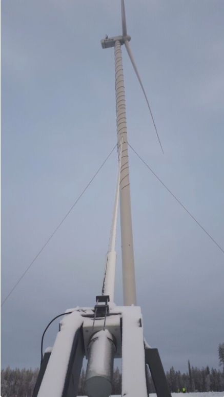
Cable stayed wind turbines towers

The use of cable stayed wind turbine towers is somehow unusual.

They are however relevant when very high steel towers are used (from 100+ meters to the current record, 175m).

An example can be seen in the picture below.

They have been taken by Peikko, a Finnish company in charge of the design and construction of the wind turbines’ foundations.

The engineers at Peikko are very experienced and they have developed several interesting projects (see for instance their rock anchor solution).

They are also very nice and easy to work with (and if you wonder what is the logo of the company, a Peikko is a mythical creature, similar to a troll).

Cable stayed wind turbine

The way a cable stayed structure work is similar to a beam with a certain number of intermediate supports. This shortens the span of each element.

The pictures below are taken from a book on bridges from Javier Manterola, one of my favourite structural engineers.

The first is a cable stayed bridge:

The same concept is applicable to a suspension bridge:

The main difference between both concepts is that the suspension bridge requires a heavy overhanging cable (in red in the image).

This cable “collects” the vertical forces from the suspension cables.

By doing so a suspension bridge avoids the horizontal forces - one of the main problems of the cable stayed structures.

In the case of bridges we are supporting the structure from the top with tensioned cables – a very efficient solution.

In the case of wind turbines towers we are supporting a structure from the bottom.

The main force acting over a wind turbine is a massive bending moment, created by the horizontal loads of the wind on the blades.

The tower is behaving as a vertical cantilever fixed at the foundation.

Using cables we are creating a fixity point in the middle of the tower. This reduce the bending moment at the bottom.

The structural scheme would be as follows ("before" the cables on the left and "after" the cables in the right):

Structural scheme of a cable stayed WTG tower

The fixity point created in the tower by the cables reduces significantly the bending moments on the tower.

This allows using smaller diameters for the towers, with strong savings in material and transport costs.

It also makes possible using towers with very high hub heights.

However, there are not only advantages.

Some problems with this solution are:

  • Additional foundations for the cables are needed. These satellite foundation for the cables are taking horizontal and vertical (upwards) loads, complicating its design.
  • An interface element is required to anchor the cable in the tower.
  • Cables need to be pre-stressed - this could create delays the installation.
  • The topography in the area needs to be flat to avoid stiffness differences between the cables (this could happen is they have very different lengths).
  • Aerolastic phenomena in the cables need to be considered in the design.

Interestingly, in this project both cable stayed towers and helical strakes are used.

Another company who has worked at this concept is Mervento (curiously, another Finnish company).

Mervento cable stayed tower

Gap or no gap? The new IEC61400-6

How to optimize the design of WTG foundations?

As wind turbine loads and foundations size keep increasing year after year sharpening the geotechnical calculations and modelling correctly the interaction between soil and foundation is becoming a priority.

The cost of foundations can represent a significant percentage of the investment in a new wind farm - even more in 2021, when steel and concrete are becoming every day more expensive.

An important topic that is becoming the focus of detailed studies is the soil bearing capacity degradation under cyclic loads.

This subject has been incorporated in the new version of the standard IEC61400-6 on Wind energy generation systems in Part 6: Tower and foundation design requirements.

Now, under certain conditions, a certain amount of "gap" below the foundation may be allowed.

“Gap” means that under certain situations the ground below part of the foundation might become uncompressed – as if the foundation was partially lifted, creating a "gap" (i.e., a separation between the structure and the soil).

This is something that previously was not allowed (unless the foundation was on rock).

The reason is that if the soil goes through several cycles of compression and decompression its bearing capacity might deteriorate. Basically the bearing capacity becomes lower and lower, putting at risk the stability of the structure.

This is a relevant change, as the IEC standard is one of the most important document (if not the most important) used in wind turbines foundation design.

The key idea behind the change is that if the soil below the turbine is not susceptible to the phenomenon of degradation under cyclic loads a certain amount of gap can be allowed.

Removing this “no gap” requirement means that a significant reduction in the diameter of the foundation can be achieved.

This happens because otherwise the foundation would have been bigger only to keep the soil below it always compressed.

The “no gap” requirement used to be one of the dimensioning constraints in wind turbines foundation design when the soil was good.

The key to allow some gap in the foundation design (and as a result, a smaller foundation and savings in concrete and steel) is to be able to justify that the soil characteristics will not will not degrade under cyclic loads.

This involves dynamic tests, which are time consuming, expensive, difficult to implement on site, unusual for most geotechnical companies and difficult to post process and interpret.

In some cases, even with a robust testing campaign, additional finite elements models have to be created to validate the design.

Will we see smaller foundations after this change in the IEC? We will need to wait several months to answer this question.

Anchor cage design standard assumptions: is there room for optimization?

Since some years ago almost all wind turbine manufacturers (“OEM” - I hate acronyms) have modified their tower to foundation interface.

The previous technical solution to connect tower and foundation was based on an embedded steel section (like a “ring” inside the foundation).

It did not work properly and the issues caused by this element might be easily subject of several articles, about the problems caused by the ring and on the solutions developed to fix those problems (i.e. retrofitting and repairs works necessary to ensure the necessary lifetime of the turbine foundations).

In the last years (I would say since around 2010) the embedded ring has been replaced with a pre-stressed anchor cage, as shown in the following picture:

The design methodology for this element is usually based on simplified hypothesis:

The first assumption is that the tensile/compression strength on each element is calculated assuming a uniform load distribution, usually using formulas such as:

T = 4Md / (n*D) + N/n

Being

T = Maximum tension force on the more loaded bolt

Md = Bending moment from the tower

n = Number of anchors

D = Average diameter of the anchor cage

N = Axial force

This is usually known as the “Petersen approach”.

Petersen is a German engineer who wrote a book about steel structure design appropriately titled “Stahlbau” (“steel construction” in German) where this calculation method is presented.

The second assumption is that the tensile force is distributed between concrete and steel if there is no decompression.

If decompression happens (something that will always happen under ultimate limit state factored loads) all the tensile force will be taken by the steel.

The only problem with this approach is that the first assumption is only true in case there is no decompression.

This approach leads to conservative results, as it does not account for the force re-distribution due to the stiffness change when decompression occurs.

However, it is very easy to obtain the maximum tension the more loaded bolt or to calculate the needed number bolts or their dimensions for a given tension.

When decompression occurs the stiffness in the “compressed” side and in the “tensioned” side stops having the same value, as the concrete stops providing its stiffness (this is the magic of pre-stressing, before de-compression the concrete is somehow taking some tension, a thing that concrete rarely does).

In the compressed side we will have an area of concrete under compression and bolts in tension (due to the prestressing), that take the compression by de-tensioning.

In the tensioned side we will only have the bolts in tension.

Similarly to a hyper static structure the stiffer side (in this case the one under compression) is able to take more load.

This works like a beam supported by springs:

In the picture on the left all the springs have the same stiffness. This would be the current design model, as in the formula shown above.

In the picture on the right the tension springs (right side of the beam) have only half the stiffness.

This is just to show how stiffness affects the force distribution, in a real anchor cage the loss of stiffness when decompression occurs might be over 80% as the concrete area contribution it is much bigger than the bolts area (total stiffness would be Es*As+Ec*Ac, being Es and As the area and elastic modulus of steel, and Ec, Ac the ones from concrete).

The “softer springs” on the right take less load, that is redistributed to the more rigid area on the left.

Please note that this would not happen in an isostatic structure (with only two supports)

As the neutral axis moves, the redistribution of forces changes. This lead to a non-linear calculation.

To perform this analysis we can implement a model with a homogenized concrete-steel section, and with variable parameters depending of the location of the neutral axis. Using this type model, we would be able to obtain the maximum stress on concrete and the tensile force on the pre-stressing element.

This way the anchors size may be adjusted, and we will get a more accurate value for the concrete compression which is slightly underestimated with the current models.

I am not going more deep into this boring details about calculations but I think that it is interesting to know that there is still room for optimization in anchor cage design.

Nearshore wind turbines foundations

Near shore wind turbine foundations

Nearshore (or “intertidal”) foundations are not a usual type of foundations.

It is a hybrid solution, an on-shore foundation in a quasi-offshore environment.

I have heard about this type of foundations several times in my career. The first time it was a preliminary design that I have made about 10 years ago for a Chinese project.

In the last years I have seen it used in several Asian countries, for instance in Vietnam (in the Mekong delta, in a project appropriately called Dong Hai 1 “intertidal wind project”).

The typical application of this kind of foundations are the shallow waters of the continental platform, using an on-shore wind turbine nearby the coast.

During the low tide, the foundation is exposed to the air while it is partially submerged in seawater during high tide.  This is an extremely aggressive environment for both concrete and steel.

Additionally, in sandy beaches with muddy underground the foundations may require piles of exceptional length (>30 meters).

The technical solutions that can be used for these special locations are typically three:

  • Mono-piles
  • Pile foundations
  • Sheet-piling cofferdams

Monopiles are the standard foundation used in maritime structures. It is a driven steel pile with a diameter up to 6-8 meters.

The wind turbine tower can be bolted directly to the monopile element without a transition element (this is often the cheaper configuration).

This type of configuration has even been considered also for on-shore projects as an alternative to pile foundations.

It has, however, several risks related to the pile driving process and the type of equipment required.

Monopile wind turbine foundation

The piles foundation with an elevated pile cap is another interesting solution.

It consist on a set of driven piles (concrete or steel) joined together by a concrete pile cap.

Interestingly, in some cases the foundations are connected to the coast (or even between them) with walkways.

This help servicing the wind turbines without using ships.

WTG piled foundation with an elevated pile cap

Another alternative that has been used is using cofferdams to create something similar to a small island, and then build the foundation inside this element by means of a gravity or pile foundation.

This construction technique is inherited form bridge construction. Since the time of the Roman Empire sheet piles and cofferdams were used to build the piers of a bridge inside a river or lake.

Cofferdams WTG foundations

IEC 61400-6:2020 Tower and foundation design requirements: a new Design Code is in town!

The IEC (acronym of International Electrotechnical Commission) has just released a new design code. More precisely it is a new section of an existing code, the IEC61400.

The IEC is an international organization that prepares and publishes international standards for all electrical, electronic and related technologies, including energy production and distribution devices.

The IEC 61400 is a set of design requirements developed specifically for wind turbines – to be sure that they are appropriately engineered against damage from different type of hazards within the planned lifetime (currently, 20 to 30 years). If you are familiar with the wind business you will probably know that this is one of the key international standards.

The IEC 61400 has several sections.

Section 1  deals with the wind turbine loads (more precisely, “design requirements”) in most of the world. A relevant exception would be Germany and some of neighbouring countries, where DIBT is used.

The new section released is the IEC 61400-6:2020 Tower and foundation design requirements.

If you are a wind turbine foundation designer, you are already aware that there is not really and internationally accepted design reference for wind turbines: there are some national references (such as the French CFMS Recommendation, or the Chinese FD 003-2007), some guidelines from certification bodies (such as the DNV guidelines), and recommendations from associations (AWEA for example has a recommendation for foundation design, but not a specific code for wind turbine foundation).

If we assume a similar applicability of this code as the one from the IEC61400:1 my opinion is that this is going to be one the more relevant technical reference (if not the most important) in the market for the next few years.

I am not going to enter deep into the technical detail of this standards, but there are a few points I would like highlight:

  • The new standard specify that foundation gapping does not need to be the limiting factors for foundations in all the cases. This opens the option to reduce the foundation size importantly when the soil is good enough.
  • Specifies the applicable codes for concrete design and provide guidance in how to perform some calculations (for instance cracking, dynamic shear modulus, etc…)
  • Has a set of very interesting annexes providing specifics about seismic calculation, strut and tie modelling, rock anchors, etc…
  • Specifies that there should not be decompression of the tower flange under the extreme (un-factored) loads.
  • Provides guidance about how to apply the sub pressure and perform the equilibrium verifications (this may modify some existing practises in some countries).

There are several interesting sections in this code, and many about towers and concrete towers that I have not yet analysed deeply but it seems that we might see some changes in the way we design at the moment.

It looks somehow unusual that this code has been issues by an Electrotechnical Commission – given the subject, it looks more like a code that should have been created by an institution of civil/structural engineers.

However I also believe that this type of reference and guidance was much needed in the sector, so I am happy that the IEC had taken the initiative of releasing such code.

Non linear finite element design on wind turbine foundations

Wind turbines foundation cracks calculation

The design of wind turbine foundations is currently based on the plate theory.

“Plates” are plane structural element and the theory (or “theories” - there are at least two currently used) calculate stress and deformation when the structure is loaded.

During the analysis several difficulties emerges in satisfying equilibrium, stress-strain relations, compatibility of strains and boundary conditions. Theoretical results are often less accurate than you might expect.

These difficulties increase when the classical theory (the one usually used by foundation designer) is applied to reinforced concrete slabs.

This is due to several aspects such as:

  • The non-homogeneous nature of concrete
  • The nonlinear response of the material
  • Cracking
  • Time effects

The use of classical elastic plate theory, therefore, has been limited to reinforced concrete slabs under low levels of stress.

Classical elastic theory fails to predict either the yield moment capacity or the load-deflection behavior of reinforced concrete slabs.

Basically, the problem is that the stress distribution that we consider in our foundations project may be inaccurate due to the existance of cracks in concrete.

These cracks appear when the concrete is subjected to tensile stress.

Once the concrete cracks the stiffness of the section changes (it reduces importantly) and the forces in the section redistribute to other stiffer regions without cracks.

Subsequently, these stiffer regions may also crack after receiving these “extra loads”.

Then, that section continues the redistribution until you reach convergence and equilibrium.

Almost no wind turbine foundation designer is yet considering this effect, that should be, in most of cases, beneficial as the redistribution reduces the stress in the most loaded areas.

Why is that?

Basically because it requires a more complex and time consuming analysis.

The models required to consider these type of effects need to include the reinforcement. This can only be obtained using an iterative process.

You also need to take into consideration the crack propagations, and the bond-slip behaviour of the reinforcement (the tension in concrete, the tension stiffening of the reinforcement, and many other phenomena that may modify the final results).

Furthermore, the models used for wind turbine foundation design include always a contact non-linearity because the foundation may have a gap (that is, partially “lifting” under certain load cases creating uncompressed areas below).

Adding the sectional nonlinearity to the steel - concrete contact nonlinearity already considered may increase importantly the calculation times.

Additionally it is not completely clear how to implement the fatigue verification to the steel and reinforcement considering this type of analyses.

Nevertheless, taking into account the size of the foundations we are reaching in the market, this type of analysis may reduce the quantities in the foundations, making them more efficient.

The importance of the geophysical survey for a Wind Farm

Today we speak about geotechnics…yes!, geotechnics, that activity that sometimes sounds strange but is so essential for the development of a proper wind farm project.

More specifically, we will see in detail tomographic refraction tests and MASW analysis.

This information is key for wind turbine foundation design but also can be needed for several other activities, such us for instance estimation of excavation (earthworks cost is linked to the hardness of the materials) and seismic design.

Geophysical works for a Wind Farm in Egypt, 2021

The analysis of the elastic modulus had been typically done with laboratory tests until a few years ago, when geophysics techniques began to be widely implemented (sometimes with unclear goals and misunderstood results).

The main advantages of these on site tests are:

  • Characterization of real terrain conditions taking into account the large magnitude of the structure it will support and its three-dimensional behaviour, rather than extracting small samples that could be not representative of the system as a whole
  • The possibility to obtain the dynamic parameters of soil stiffness, which are often the dimensioning factor due to the need to achieve a certain rotational rigidity for the wind turbine

It is important to highlight that some soils don´t seem to be apt to withstand the ever-larger loads of today's wind turbines if they are tested using “classical” methods (odometer, triaxial, etc…).

However, the same soils show a better performance when geophysical techniques are used to analyse them, mainly because they are less conservative, more realistic and more appropriate for dynamic loads and quite relevant foundation dimensions.

One more comment on dynamic parameters of soil stiffness: it´s worth noting that correlations that were widely used to estimate dynamic values from static values used to imply, depending on the type of terrain, wide uncertanties.

In some cases the values were unfavourable and did not allow to optimize the dimensions of the foundation. In others cases, unrealistic values reduced the level of safety in designs.

For all these reasons geophysical survey is strongly embedded in the way wind turbine foundations are currently designed, so the IEC 61400-6:2020 has made changes in its latest edition (see Annex L) to improve and adjust the calculation methodology.

Variation of shear modulus with soil strain

As a summary, take into account that optimization and accuracy within geotechnical calculation can lead into an optimization of the foundation, so be aware of the importance of geophysical survey for a wind farm and opt for a more comprehensive geotechnical study, appropriate to each case, modern and based on international regulatory updates.