Category: Substations, Overhead Lines & Electrical Works
-
Substation Earthing Design per IEEE 80 — Step by Step
A practical walkthrough of the calculations behind a safe grounding grid, using a real wind farm substation as an example. If you have ever opened a substation earthing calculation and found yourself lost between decrement factors, mesh voltages, and geometric correction coefficients, you are not alone. IEEE Std 80 — the IEEE Guide for Safety…
-
110kV Substation Layout: Single vs Double Busbar Configuration
How to choose the right busbar arrangement for your wind farm? Every onshore wind farm needs a grid connection substation, either an existing or a brand new one. And if you need to build a substation for your wind farm, one of the very first design decisions you’ll face — one that shapes the entire…
-
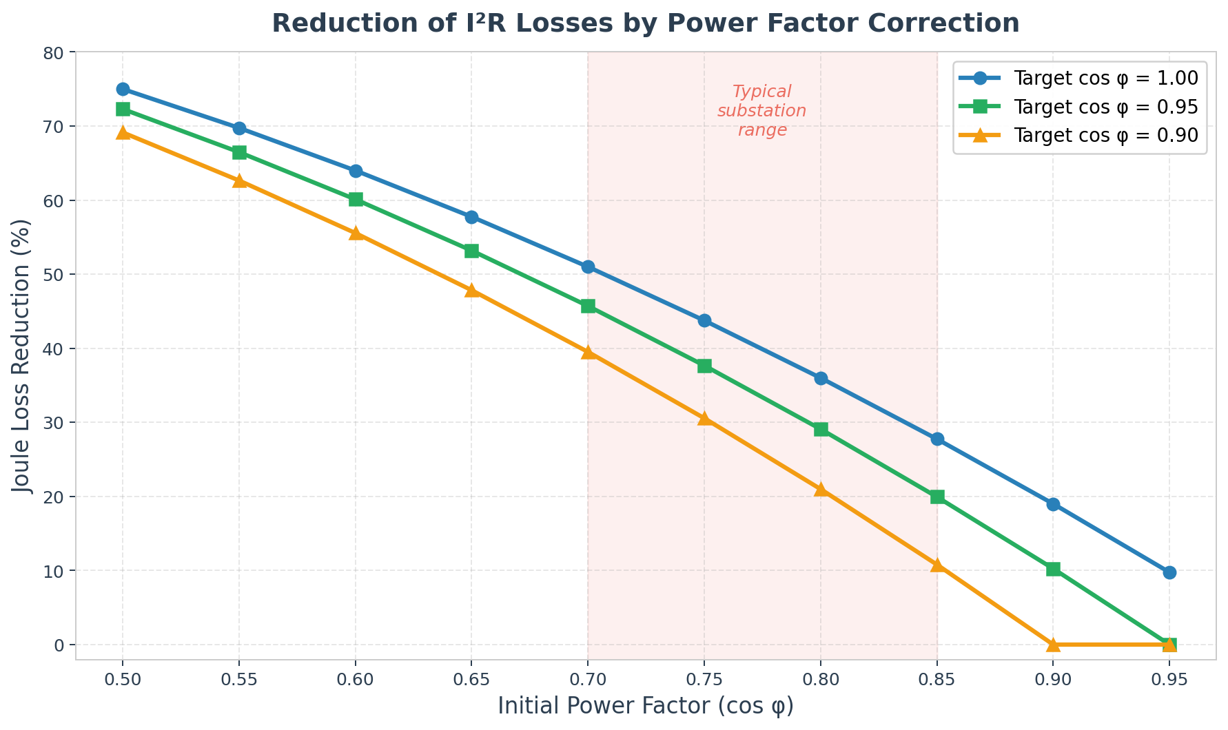
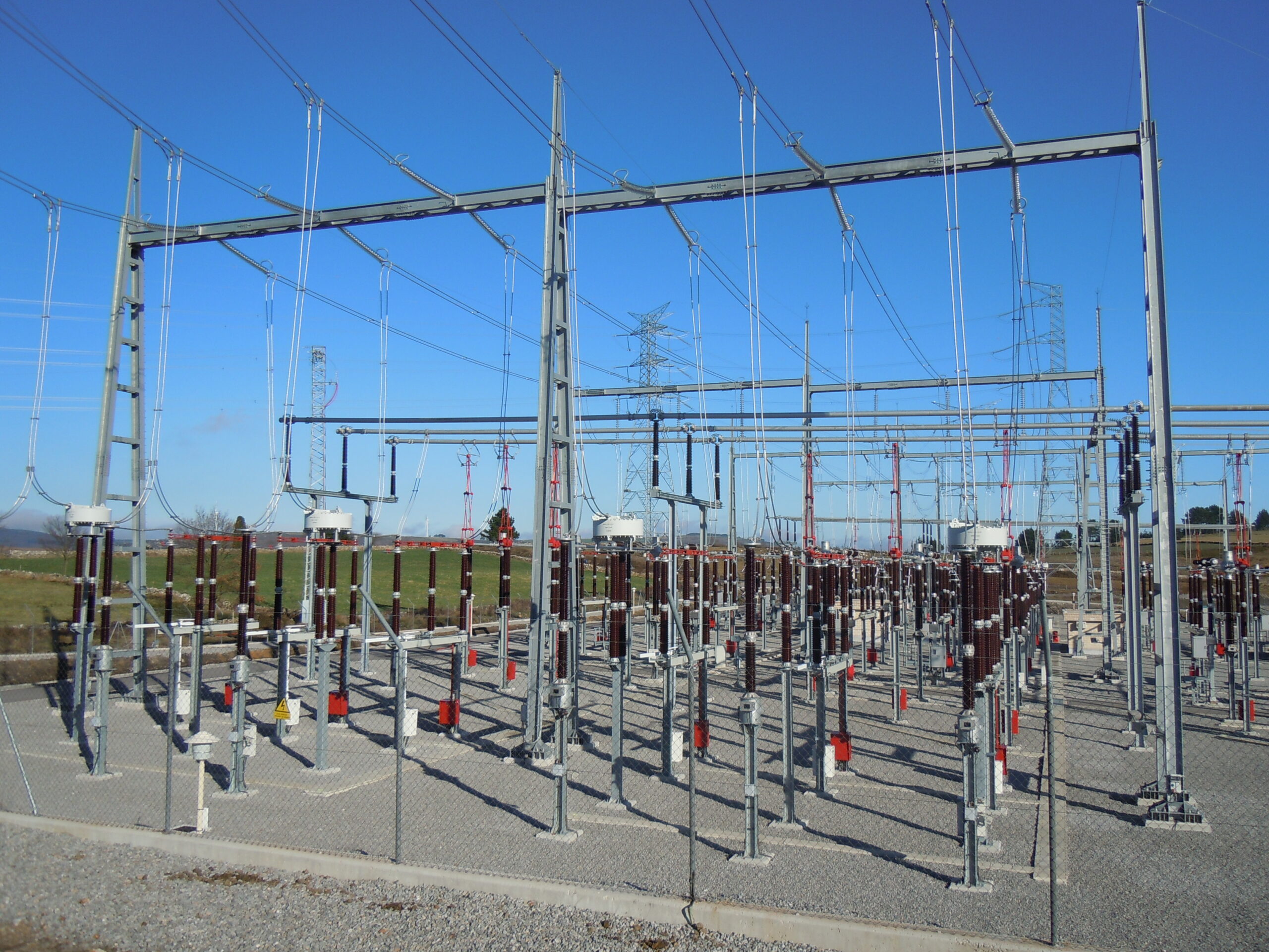
Power Factor and Reactive Energy Compensation in Wind Farms
A practical look at why capacitor banks end up in every wind farm substation, and what you need to understand about reactive energy compensation to specify them correctly. If you have been involved in the electrical design of a wind farm substation, maybe you have seen a capacitor bank in the single line diagram. It…
-
Making new friends: grid friendly wind turbines
Renewable energy is revolutionizing the global power sector, with wind energy emerging as a key player in the transition towards a sustainable future. Wind farms, harnessing the immense power of nature, are sprouting across landscapes, powering homes and industries while reducing carbon emissions. In this website we explored the advancements in wind farm engineering and…
-
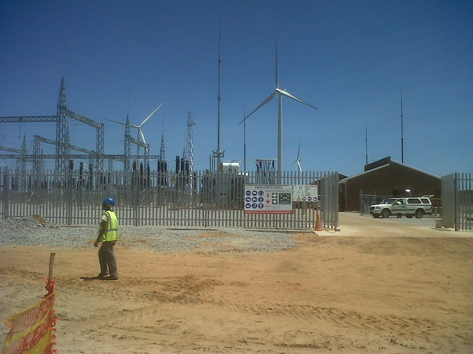
Mobile Substations for Wind Farms: When and Why
A mobile substation is exactly what it sounds like: a full medium-voltage or high-voltage substation mounted on a trailer. You have HV disconnector, HV arresters, protection fuses, a power transformer with on-load tap changer, an LV breaker, control cabinet, relays, metering: basically the whole stack compressed onto a single flatbed that a tractor can tow…
-
Medium voltage power cables in wind farms: an introduction
This post is an extension of the previous short article I wrote some years ago on the characteristics of wind farms medium voltage system. I wrote it with the help of my friend and colleague Kamran, who spent more than an hour answering my questions on the subject. Thank you Kamran! The medium voltage network…
-
Lightning protection of wind turbine blades
I have received a question from a reader regarding blades damaged by lightning. Specifically, the blade has been damaged before commissioning. At first sight the consequences could be less significant than usual, above all if the main crane is still on site and there is a set of spare blades available as happens frequently in…
-
Looking for an electrical engineer specialized in Turnkey / EPC (Balance of Plant)
If you are reading this blog chances are that you know someone who could be interested in this position… Please spread the word! Link: Project Engineer Electrical Balance of Plant-Turnkey (m/w)
-
Itemized sourcing: everybody else is doing it, so why can’t we?
Itemized sourcing is the new mantra in the business. Basically, it means that you should split the BoP (Civil and Electrical works) in as many lots as possible, in order to achieve substantial savings. This strategy is the opposite of the “single subcontractor” approach, where you give the full package to a unique contractor or…
-
Constraints to medium voltage power cables in wind farms
(This post has been updated in July 2020 with the help of my friend and colleague Kamran) I already discussed in two other posts how the wind farm cable trenches are usually built and how the medium voltage cables are made. However, a more comprehensive explanation should include on how the medium voltage cables are dimensioned. The power produced…