Category: WTG Technology
-
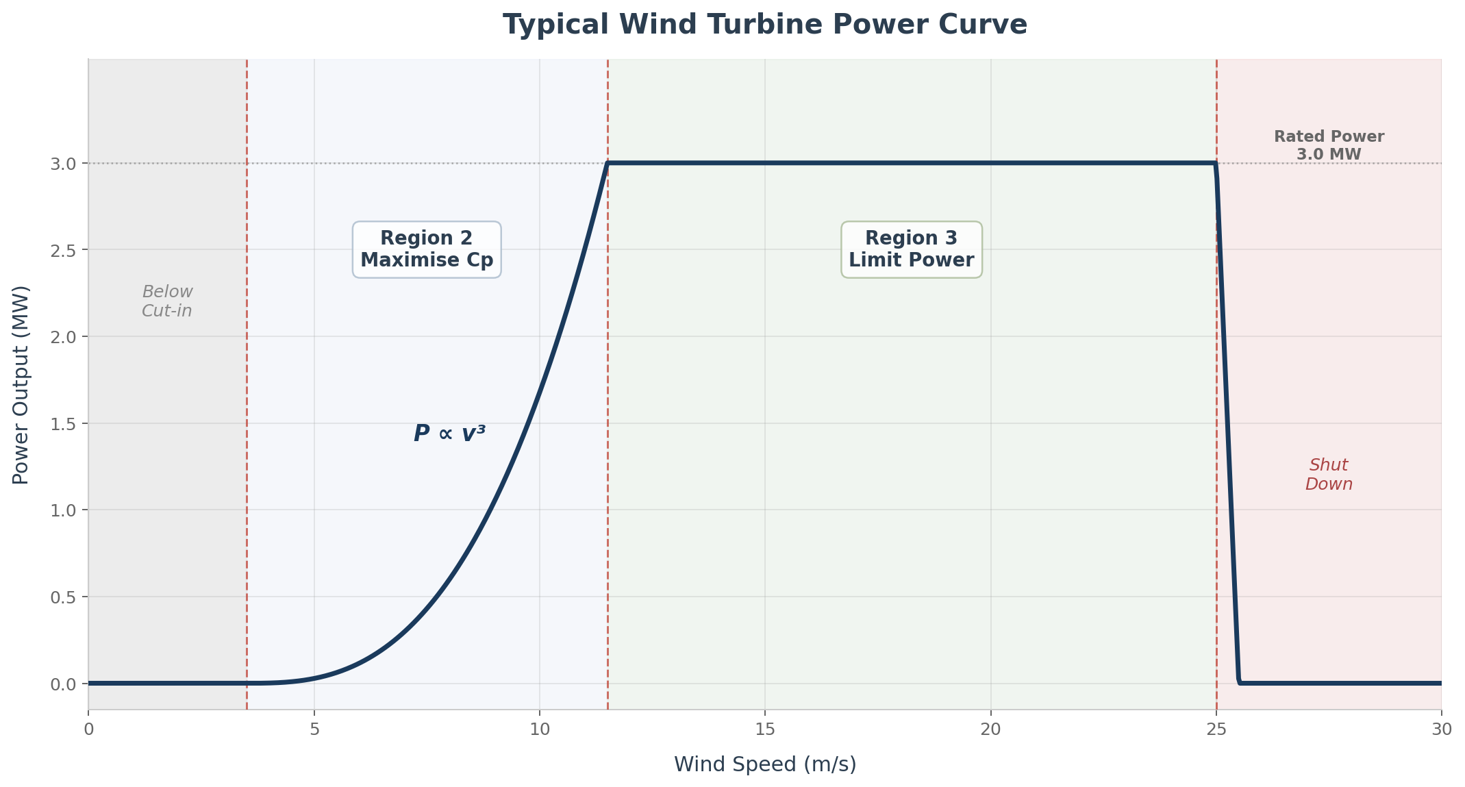
Wind Turbine Aerodynamics — How a Wind Turbine Extracts Energy
You don’t need to design blades to understand how they work. But understanding the basics will make you a better project engineer. This is an aerodynamics crash course with the practical essentials that a BoP engineer should have in their mental toolkit. Let’s start from first principles. A wind turbine converts kinetic energy from moving…
-
Making new friends: grid friendly wind turbines
Renewable energy is revolutionizing the global power sector, with wind energy emerging as a key player in the transition towards a sustainable future. Wind farms, harnessing the immense power of nature, are sprouting across landscapes, powering homes and industries while reducing carbon emissions. In this website we explored the advancements in wind farm engineering and…
-

From blades to cement – the experience of Veolia
A few days ago YouTube’s algorithm correctly has correctly suggested to me to have a link at this video. Made by Business Insiders is an interesting addition to the theme of wind blade disposal – have a look at my previous post on the topic on how to use blades to make cement. You will…
-
Do we really need towers and foundations? Airborne wind farms
Airborne wind energy is a generic name that describe various technologies that have different levels of development. They have in common the idea of using unmanned vehicles such as planes, kites, balloons or similar solutions to produce energy from the wind. These vehicles are generally “tethered” (that is, connected to the ground). Their main promise…
-
Blades repair – how to fix it
I have discussed in other posts why wind turbines blades are prone to different type of damages and how to detect them. But what happen when a problem is identified? Changing the blade is usually the “last recourse” option: in addition to the cost of the blade itself there are the transportation costs plus the…
-
Wind turbine blade damage detection systems
Wind turbine blades are rarely subject to catastrophic failures, although you can find a bunch of videos on YouTube with blades flying away or falling into pieces. They are however subject to several problems, such as cracks, debonding of the various layers, internal delamination, etc. As an order of magnitude blade failures are accountable for…
-
Can a rotor be smart? Passive optimization systems
The spectacular growth of the dimension of the wind turbine has led to the introduction of several interesting technical solutions. Different type of towers (concrete, hybrid, lattice, self-erecting, etc.) and new technical solutions for the foundations appeared in the last decade, trying to have the lowest possible cost of energy. The rotor of the turbine…
-
Vortex bladeless wind turbines
I have always seen the wind induced vortexes as a problem – they create vibrations in the tower, that in some cases can start to resonate with the eigenfrequencies (the natural frequencies of the structure) and in the most extreme cases even collapse. The existence of such vibrations is one of the reasons why it looks…
-
Wind turbine tower as a water battery: the Gaildorf Wind-Water Project
Did you ever think at the amount of empty, unused space in the bottom of a wind turbine? Any idea how to use it? Well, the folks at Max Bögl (a German conglomerate active in several sectors) have decided that it could be a good idea to fill it with water (about 40.000 m3 per turbine,…
-
Wind turbine blades damage – an introduction
I have discussed in another post the different type of damages that a wind turbine blade can suffer and the various detection systems. There is an extensive list of potential problems: cracks, delamination, debonding, erosion of the leading edge (the first area of the blade to “see the wind”) are some of the issues observed. This variety…