Medium voltage power cables in wind farms: an introduction

This post is an extension of the previous short article I wrote some years ago on the characteristics of wind farms medium voltage system.

I wrote it with the help of my friend and colleague Kamran, who spent more than an hour answering my questions on the subject. Thank you Kamran!

The medium voltage network is one of the elements that compose a wind farm project, the other being foundations, earthworks, substation and high voltage line.

Some elements could be missing: I have seen several projects without substation, for instance in France where  small wind farms were connected to the grid directly at medium voltage level. However, you will never see a project without at least several hundred meters of medium voltage cables.

Wind turbines generally produce energy with a voltage around 600V – 700V. Subsequently the voltage is raised by a transformer that can be located in the nacelle, at the base of the tower or less frequently externally in a small box near the tower.

The objective is to minimize the electrical losses, and several voltage level are theoretically possible - I have seen projects with MV levels varying from 12kV to 33kV and higher.

The objective to achieve working at the design of the medium voltage system is obviously finding the sweet spot that optimize Capex (what you pay for cables and transformers cost) and Opex (mainly the electrical losses that you will have in the cables), selecting a rated voltage compliant with local regulations and cable types that are commonly used in the country where the wind farm is located.

Cables are rated by their effective cross sectional area in mm2 – the greater the section, the greater the amount of current they can transport.

Standard sections frequently used in wind farms are 70, 95, 120, 150, 185, 240, 300, 400, 500 and 630 mm. Greater sections are commercially available but already the 400 to 630mm sections are hard to use in construction due to their weight and bending radius.

The bending radius is usually expressed as a function of the diameter. For instance, “10x D” would mean that the minimum bending radius is 10 times the diameter of the cable. This parameter is significant because you will probably need some narrow bends in your cable, for instance at the bottom of the foundation if the transformer is inside the turbine. Large binding radius can make the work at the construction site very hard.

The cables are made of several layers with different functions – many technical alternatives and constructive techniques are available in the market but in general you will find (from the centre to the most external layer):

  • A conductor core made of copper or aluminium
  • An insulation layer, usually made of cross linked Polyethylene (XLPE)
  • A metallic screen to stop the electric field
  • An external sheath, protecting the cables from corrosion, humidity and mechanical stress. In some projects this most external layer is selected to have special properties such as for instance enhanced resistance to fire or protection from aggressive chemicals or even termites (I have seen this last feature in Australia)

Different medium voltage cable layers. Copyright image Yuzh cable

Cables will be delivered to the wind farm in cable drums made of wood.

The standard design strategy is trying to minimize the number of cable drums because making the joints between different sections of cables is an expensive and highly specialized task.

There are however limits to the size of drums – basically both its weight and dimension must allow safe transport and manipulation.

The amount of meters of cable that can be transported on a drums depend on the cable type and diameter – for wind farms you will usually receive some hundreds of meters in each drum.

Single core vs. three core cables

There are two main typologies of MV cables commercially available, single core and three core.

In single core cables each comes with his own screen while in three core cables the three phases share a common metallic screen. If you select the single core technology you will need to use three different cables, one for each phase.

Aluminium vs. Copper cables

The material used for the conductor of the cables for wind farms is always almost always aluminium.

Theoretically, copper cables are available and copper has several desirable characteristics - for instance it is a more efficient electrical current conductor and requires a smaller cross section to carry the same amount of power as an aluminium conductor.

However, with the current relative prices of copper and aluminium, copper cables are simply too expensive so they are never used for the reticulation of wind farms – you will probably see them inside the substations, where distances are shorter.

The cost of raw materials such as aluminium represent a relevant percentage of the final cost of the cable. For this reason I tend to see the MV cables almost as a commodity.

Overhead vs. Buried cables

In the majority of countries, the cables are directly buried in a sand bed in the bottom of the trenches (or in very rare cases, inside a duct).

Every now and then, I see a project with an overhead medium voltage line, for instance in India or South Africa. However, they tend to be more the exception then the rule.


Slingers & trenching machines in wind farms: a guest post by Christopher James

After posting this article on Slingers I have been contacted by Christopher James, an expert on the topic with an exceptional amount of real world experience.

He has been so kind to share is knowledge on the theme and I am thankful for that. I am sharing it with you in the very comprehensive post below with almost with no edits.

You can reach him via LinkedIn or following one of these links:

https://slingers.com

http://buckeyetrenchers.com

(Beginning of guest post)

This video link shows some of the applications of the Slingers working on wind farms.

Slingers are high speed material placing machines.  By introducing them to backfill cable trenches most companies can remove one piece of earthmoving equipment, one operator and two or more labourers.

While doing all of this they are able to increase production of over 10 times faster than some operations and while almost reducing waste of the imported material.  In the  video below these speeds of backfilling are real time speeds.  The machine was backfilling cable trenches on a wind farm in NSW, Australia.


Speed is obviously an advantage but it is the ancillary savings like reduced labour and equipment.  Also the waste of the imported material is huge with traditional methods.  In some cases on large scale wind farms we are able to off-set the cost of a Slinger to just the savings alone…all on one job.

These machines can move up to 3.5 cubic meters per minute.  This is in a perfect world and perfect conditions.  Generally speaking a good average to work on is 8 to 10 meters per minute on most 400mm wide trenches.  As you can probably tell this is huge production compared with some of the old methods.

This wind farm in NSW where we brought this TR-30 Slinger (rubber tracked with cab) they were using a 25 tonne articulated dump truck and a 20 tonne excavator.  The excavator would scoop material out of the truck and place into the trench.  We were around 15 times faster than this operation with the obvious one less machine and operator.

I have also added the below the link to a video by Buckeye Trenchers working on the cable trenches on wind farms in the USA.  We are agents for Buckeye Trenchers and these really are high speed trenching machines.  A Bucketwheel trencher is suited to soils or small stoney ground.  They are not suited to rock at all.  Once you hit rock you have 2 options, either a Chain Trencher or a Rock Wheel trencher.  Either way there are options.

A chain trencher is one of the most common trenchers around the world, as seen in the Vermeer video link below.  These units can range in trenching widths from 300mm up to over 2 meters wide.  Ranging in weight from 20 tonne up to over 200 tonne.

A rock wheel trencher as shown in the video below by Vermeer will generally only go up to 350mm wide trench.  Now I have seen up to 450mm wide but not a very common machine.

Next you step up into the “dig, lay, bury” machines.

Rivard make a unit in the attached video. These are great units for single pass operation.  From experience though if one link in the chain stops, like the trencher or the cable spooling and so on, everything stops.  This can be quite costly.

From my experience having crews working on multiple fronts at once limit your risk and usually allows for a more productive environment.  For example a bucketwheel trencher should get around 3 kilometres of trench done in a shift, the same goes for backfilling with a Slinger (depending on many factors).

If you were doing a single pass operation you would not achieve numbers like this.

It really comes down to how much production you really want, or you can achieve.

Each operation has its pluses and minuses, no doubt about it.  As I was always taught in pipelines, get the basics right.  Get the equipment right.  Lower your risk as much as possible and then find minutes to shave off each process.  Laying cables is as repetitive as it comes, just like pipelines and it is all about streamlining processes as much as possible to get as efficient as possible.

This is why we have always used trenching machines for pipeline works.  They replace many excavators (bucketwheel trencher can replace up to 10 x 25 tonne excavators).  Trenchers also make exceptional backfilling material, excavators just cannot do this.

As a general rule (very general as all ground conditions change dramatically) please see the below for trenching equipment production:

  • Bucketwheel in good, dry soil ground conditions: 3 kilometers up day digging 400mm wide trench at 1.5 meters deep
  • Chain trencher in firm, dry, small stone ground conditions: 800 meters to 1000 meters per day digging 460mm wide and 1.5 meters deep with a 45 tonne class machine

I cannot give production in rock as it is too much of an unknown with the hardness and so on.

I have had 45 tonne class chain trenchers take 3 days to cut 4.5 meters of pink quartz and then dig 600 meters of hard limestone. It is too much of a variant to give some solid figures.

Additional links that you might find useful:

https://www.linkedin.com/pulse/where-how-use-my-slinger-episode-10-wind-farm-christopher-james/

https://www.linkedin.com/pulse/7-reasons-why-bucketwheel-trenchers-bring-efficiency-your-james/

https://www.linkedin.com/pulse/where-how-use-my-slinger-episode-2-trench-backfill-imported-james/

https://www.linkedin.com/pulse/stop-wasting-money-when-backfilling-your-trenches-imported-james/

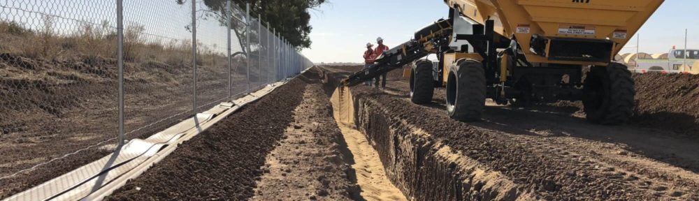
Rock slingers for a quicker trench sanding & backfill

This morning I found by chance this very interesting website (well, it is interesting if you like wind farm constructions…).

Basically it is an Australian company using “rock slingers” (that is, conveyors belts connected to a dumper) to backfill trenches mounted on small vehicles (2.5 meters wide). The equipment is made by CAS, an American company specialized in this kind of equipment.

It is a remotely controlled machine that can create the sandbed inside the trench accurately and at a great speed. According to the figures provided in the website the slinger can create 16 Km of bedding in a day, using up to 1000 tonnes of material.

I guess that they call it "slinger" because it can throw material at a quite remarkable distance (over 40 meters). Used in combination with one or two trencher it looks like it can lead to relevant savings, less labor and a more homogeneous distribution of the material.

EDIT (18/12/2019):

I have received an email from Penelope Smith from Rockslinger on the topic. As I beleive it can be interesting for several readers I'm including it in the post below.

Hi Francesco,
We are involved in many civil projects involving backfilling trenches and 'Rockslinger' is our trademarked brand of high speed conveyor equipment in Australia. It's super to see the machinery becoming noticed in the renewable energy sector, such as the other operator you mentioned in your blog.

Our site is www.rockslinger.com.au and we are the largest slinger fleet operating in the country. This type of machine actually speeds up the process of installation at the trench and material spreading stage incredibly using this equipment.

It has a movable arm and is externally operated if needed with advanced drive ability. The application rate is a tonne a minute accurately laid at the contractor's required depth.

We have found that the renewable infrastructure sector in Australia, including wind farms and solar farms, are beginning to realise the saving in construction when using more efficient machinery. I've had a read through your blogs and really appreciate you sharing your experience.

Now I've found your site, I'll keep an eye out for the next blog. Thanks again.

Wind farm earthing and optical fiber cables

In this post of many, many years ago I explained how wind farm trenches are usually built.

In addition to the medium voltage cables, in the trenches usually there are also 2 other type of cables:

  • Earthing cables
  • Optical fiber cables

The earthing cables are usually made of copper and they are used to dissipate fault currents, coming usually from lightning or short circuits.

Typically the earthing cables connect all the wind turbines with the substation. In the turbine side, they are usually connected with an earthing bar inside the tower.

Additionally, there is also a second earthing system inside the foundation connecting the earthing bar with the steel rebars inside the concrete.

This system usually grant low earthing resistance (<10 Ω) in the majority of cases. In specific situations (for instance, wind turbines in rock with high resistivity) it can be necessary to use additional measure to lower the resistance, for instance using several auxiliary copper rings around the foundation.

The optical cables bring all the information recorded in the wind turbine and the met mast to the SCADA system. Usually there is a software installed in a specialized server in a separated room of the wind farm substation.

From there, the information reach the stakeholders via an internet connection (usually there are remote control centers).

The fiber optic cable usually have from 4 to 16 fibres and, due to the distance, they are usually single mode. The topology of the optic fiber cables connection depend on the redundancy asked to the system. If you really want to avoid the risk of losing control of the turbine in case the optical fiber is damaged somehow, then the correct solution would be a redundant ring topology where a WTG is connected to the SCADA system following 2 different paths.


Constraints to medium voltage power cables in wind farms

(This post has been updated in July 2020 with the help of my friend and colleague Kamran)

I already discussed in two other posts how the wind farm cable trenches are usually built and how the medium voltage cables are made.

However, a more comprehensive explanation should include on how the medium voltage cables are dimensioned.

The power produced by the wind turbine is usually evacuated to the substation using a medium voltage (MV) cables connection.

This cables are usually buried. This solution is slightly more expensive but it offer much more protection to the cables than an overhead line (that is, a line where the cables are hanging from poles). A buried circuit is also less problematic from the environmental point of view. I do however see every now and then projects with overhead MV systems.

The reason for evacuating the power generated by the wind turbines with a medium voltage system is purely economic. A low voltage solution would have very high power losses (“Joule losses”) in the cables – basically the resistance of the conductor would create too much heat.

A higher voltage will decrease the current flowing in the cables and the related losses.

However, high voltage equipment is very expensive. Therefore, the medium voltage solution is a reasonable compromise, an optimum balance between the losses in the cables and the cost of the equipment.

So, what are the key constraints in the design of a MV system for a wind farm?

In many projects there is some freedom on the MV level used in the wind farm – that is, you can design a MV system using one of the standard voltage levels (such as 20 kV, 33 kV, 34.5 kV, etc.)

In situations where there is no specific requirement from the owner of the wind farm (or from the owner of the grid) the smartest choice is usually to select the MV level most commonly used in the country where the wind farm will be built.

Sometime the number of feeders in the substation is defined upfront: this limit the number of different circuits that can be designed to connect the wind turbines.

Another relevant limitation is the maximum allowable cable cross section: the bigger the cable diameter, the bigger the bending radius. For this reason cross section over  630 mm are very unusual.

For a given cable section you will try to maximize the amount of current transported without exceeding the thermal capacity. Under standard operation conditions such limit is usually around 90°C and the thermic behaviour of the cable will be obviously strongly influenced by the thermal resistivity of the surrounding material. Other relevant parameters are the depth of the cable, the temperature of the air and of the surrounding material, if there are other circuits nearby, etc.

Other significant project constraints that must be checked are the allowable current (how many amperes are transmitted by the cable – to be sure that the capacity of the cable is not exceeded) and the voltage drop between the 2 sides of the circuit (usually it should be less than 1.5%).

You will also try to minimize the power drop. A rule of thumb is that the losses should be less than 2%, but some wind farms have more aggressive requirements.

Last but not least, additional checks are performed to ensure the survival of the cable in emergency conditions – for instance in case of short circuits.

The short circuit currents are checked against the cable ratings under a variety of possible faults (phase to phase, phase to ground, etc.). Cables are designed to survive a higher temperature for a very short periods (seconds, or fraction of a second).

Trenchers in a wind farm: do they make sense?

In a nutshell, the answer is yes – at least if you are able to find one nearby at a reasonable price.

In general, you will have several alternatives to dig your cable trenches:

  • Backhoe
  • Backhoe with hydraulic breaker hammer
  • Explosives
  • Trencher

The smarter choice will depend on the hardness of the rock.

In general, the use of explosive for trenches in wind farms is extremely rare – it is normally limited to foundation excavation.

Backhoe is always an easy solution, above all in situation where the trenches follow a very irregular path with a lot of change of direction.

However, it’s production is lower when you have compact, very hard rock (for instance, basalts and granites).

On top of that you can have a border of the trench which is not very “clean”, as it could be difficult to open a truly rectangular section.

All in all, it will usually be a better choice in small wind farms on soils or soft,, fractured rock.

The biggest problem with trenchers is that it’s not always easy (or cheap) to find one for your project. They are very performant with long distances, as they can easily open from 1 to 3 meters per minutes in soils (e.g. silts and clays).

Obviously they are somehow slower in rocks. In a very soft one (e.g. gypsum) you should work at a pace of around 1 meter per minute (from 40 to 80 m/h), going all the way down to few meters per hour while you go up in  the Mohs scale.

As an order of magnitude, in limestone you would get from 15 to 40 meters per hours, in sandstone from 10 to 30 m/h and in gneiss less than 10 m/h.

Horizontal directional drilling (HDD) in wind farms

Horizontal directional drilling is a technique frequently used in wind farms when we have the need to cross the pipes below roads, rivers or even the sea.

Here you have the picture of 2 slightly different solutions, one using directional drilling and the other with horizontal drilling.

The installation of a pipe using directional drilling (also known as HDD, slant drilling, or deviated drilling) consists of three stages:


1.            A first drilling, with which you will realize a “pilot hole” with a smaller diameter.

2.            Hole enlargment, using one or more reamer with a diameter bigger of the cable to be installed (normally 1.7x), achieving the width required for pipes installation. This is done coming back from the exit hole.

3.            Pipe laying service, pulling them out from the exit.


To guide the drilling head, an electromagnetic wave transmitter is used, so that its position is known exactly in every moment. Several data are transmitted, such as position, inclination, temperature, etc. The signal can be read up to a depth of 15 meters or more.

The fluid used in the perforation may vary. Normally bentonite is used, but due to environmental issues (for instance if it's necessary to cross a water body) low pressure compressed air is often used as alternative.

There is also an "office" work developed before, where a stratigraphic map as detailed as possible is prepared using the info collected with several boreholes to define what material you should cross in every position.

Of course this technique is more expensive than traditional trenching. Depending on the country and length of the perforation it can be between 5 and 10 times more expensive.

In the “standard” direct horizontal drilling the solution is easier: we’ve made 2 holes, one on both side of an existing local asphalted road, and then we’ve realized a simple horizontal perforation. Here the distance is around 12 meters, while horizontal directional drilling goes often to bigger length (hundreds of meters, up to our record that is almost 1 Km).

Cable trenches layout design

We try to design cable trenches as straight as possible, avoiding pronounced angles.

There are several national norms on the minimum bending angle, for instance UNE 20435/2 in Spain.

For environmental and technical reasons we try to design the trench parallel to the access road. When we have to cross an obstacle such as an existing asphalted road or a river, a standard solution is the horizontal directional drilling (HDD). We also try to limit the number of times we have to cross the internal roads, and when the cross section of the road is on halfway (with cut on a side and fill on the other) we put the cables on the cut side.

The depth of the cables seeks a balance between 2 factors: heath dissipation (easier when the cable is near the surface) and humidity, normally increasing with the depth.

Normally the cables are buried directly in the trench: only when they cross a road or enter the WTG trough the foundation they are protected with a plastic pipe (a standard diameter is 16 cm). In this case, it is normal to leave an empty pipe as a backup.

Regarding manholes several wind farms use them (for instance I’ve seen a number of Gamesa wind farms with manholes), while Vestas don’t consider them necessary.

We also mark with concrete milestone the position of the cables, to find them again when the vegetation growth.

Below you can find an example of the single line diagram we use to work and a standard cross section (proposed for a project developed by Dong).

Medium Voltage Cables Optimization

The optimum design of the medium voltage (MV) cables consists in finding the best compromise between the initial cost of the cables and the total energy loss of the system.

For this reason we design wind farms with a radial network, and section of the cables decreasing from substation to the most faraway point of the wind farm: the lesser the distance from the substation, the greater the amount of energy carried by the cables.

Furthermore, the resistance of the cable depends on his temperature, and the temperature depends on the current.

Normally cable section is decided after an iterative process: cable section depends on the prospective short circuit current, which is related to the cable section, voltage drop and losses and last but not least the cost of the cable itself.

To simplify the problem one of the simplifications is to consider all the WTGs exposed to the same wind speed for the same number of hours. This hours will be determined by the Weibull distribution of the wind farm.


Cable trenches - the nervous system of the wind farm

Cable trenches construction probably doesn’t looks like the most exciting things in life, but including for them there are things that is better to know to avoid mistakes.

They are used to connect the WTGs together with medium voltage cables, and they bring the earth and the optical fibres cables as well.

The standard construction sequence is as it follows:
After the opening of the trench, on the bottom a layer of sand 10 cm thick is spread, placing above it the medium voltage cables, the ground cable and the optical fiber cable.

Subsequent to the positioning of the cables another layer 30 cm thick of fine sand, washed and compacted properly, is extended.

Above this second layer it will be placed, throughout the entire length of the trench, a HDPE cover tile marking the presence of underground cables.

The cover tiles will be placed directly above the filling that covers the cables. It has a function of mechanical protection of the cables, signaling the proximity of the cables in case of reopening of the trench.

On this tape will be extended another layer 50 cm thick, using native material coming from the excavations free of stones, branches and roots, properly compacted in layers of no more that 20 cm in thickness of loose material before compaction.

After completing this layer it will be positioned a PVC warning tape informing of the existence of medium voltage electrical cables under it.

Finally, the backfilling of the trench will be completed with a layer of 30 cm using material coming from the excavations, free of stones, branches and roots, compacted properly. The last layer of backfill will be done with topsoil coming from the excavation and previously stored properly, in order to recover the natural environment of the area as soon as possible.

In the following pictures the main elements of the operation are shown.