Author: Francesco Miceli
-
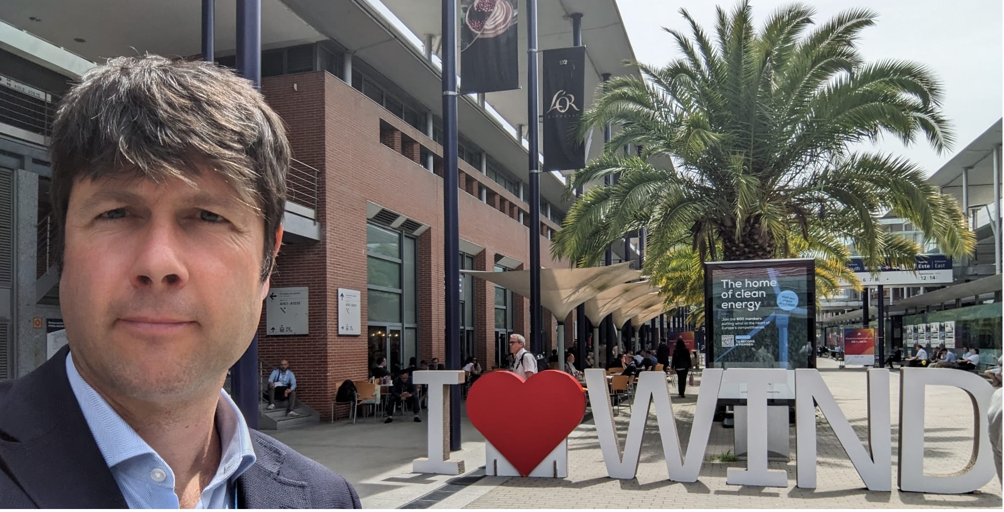
WindEurope Madrid 2026
Last week I had the chance to travel to Madrid for windeurope, where I had the pleasure of reconnecting with many friends, colleagues, and former coworkers. People with whom I’ve shared projects, challenges, and long days (and nights) on wind farms across different countries. Among others I met Jesus, now at OceanWinds, Alessio and Ignacio,…
-
The interface problem: scope gaps in wind farm construction
If you decide to divide the work on building your wind farm among several companies, you will likely save money. However, the trade-off will be coordination issues. This is the problem that shows up when two subcontractors are standing next to a half-finished cable trench, each one explaining why the other should complete the work….
-
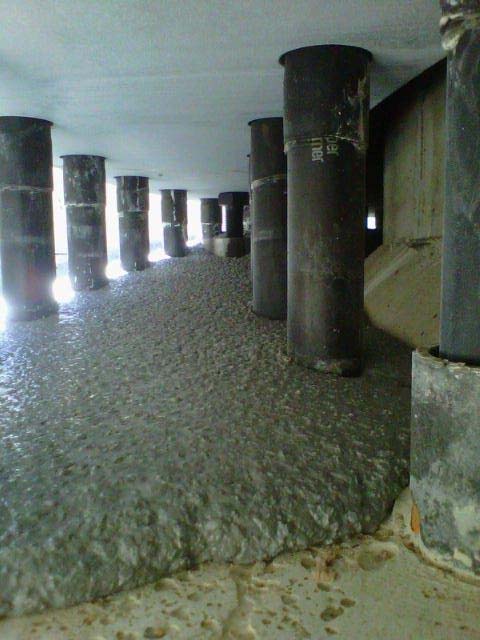
Grouting the Tower-Foundation Interface — Materials, Process, and Quality Control
The small layer that carries the full weight of a wind turbine — and why getting it wrong can be catastrophic. There is a thin layer of material between the steel tower of a wind turbine and the concrete foundation it sits on. It is typically 20 to 50 millimetres thick, it weighs less than…
-
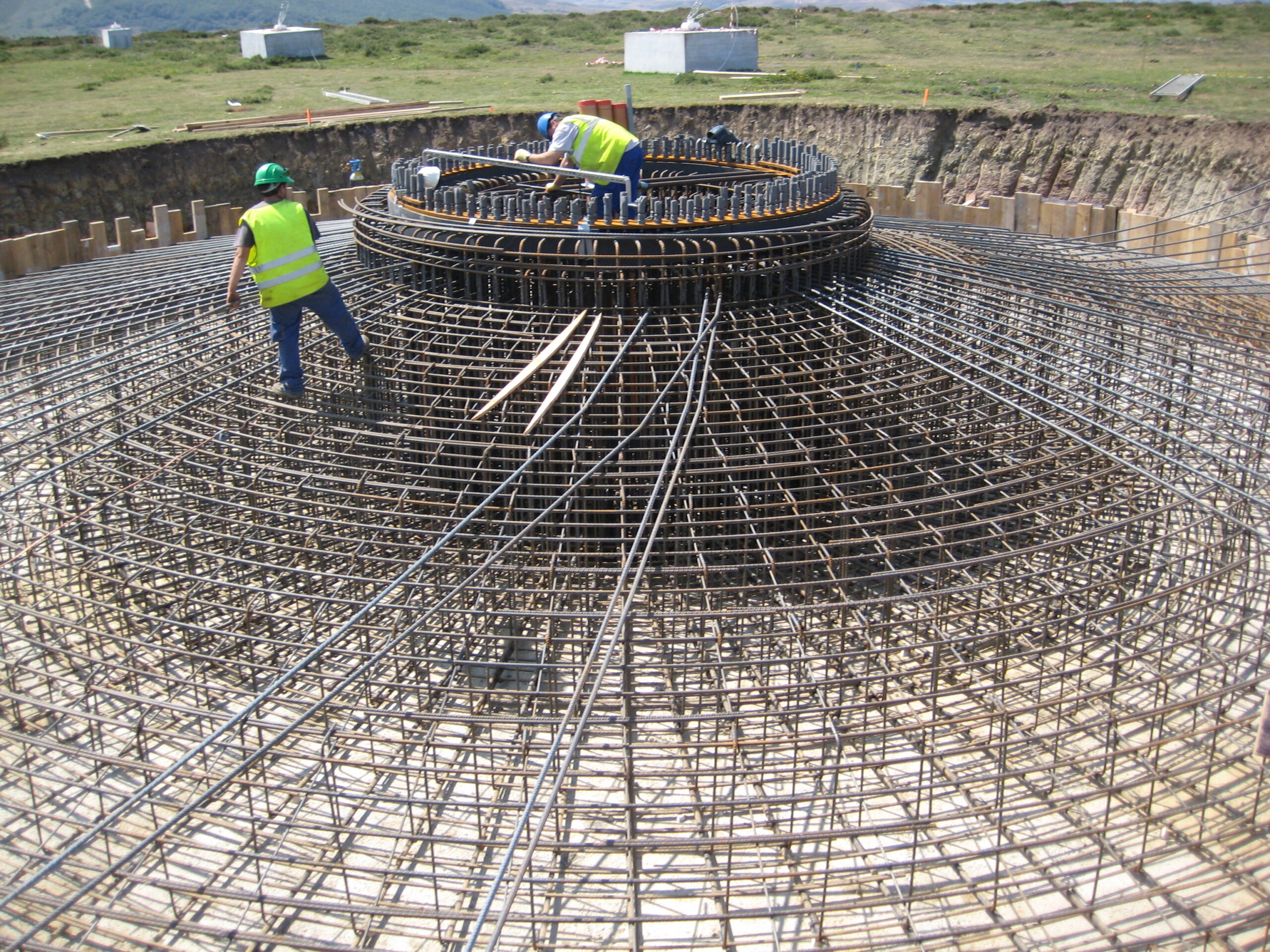
Wind Farm Foundation Repair: A Real Case Study
When a gravity foundation cracks, how do you diagnose the problem, design the fix, and execute the repair — all while the turbine stays in place? Wind turbine foundations are designed to last 25 to 30+ years, matching the operational life of the turbine. They are massive reinforced concrete structures, typically buried several metres underground,…
-
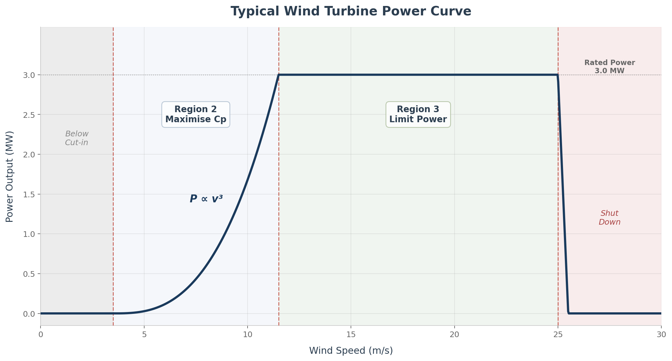
Wind Turbine Aerodynamics — How a Wind Turbine Extracts Energy
You don’t need to design blades to understand how they work. But understanding the basics will make you a better project engineer. This is an aerodynamics crash course with the practical essentials that a BoP engineer should have in their mental toolkit. Let’s start from first principles. A wind turbine converts kinetic energy from moving…
-
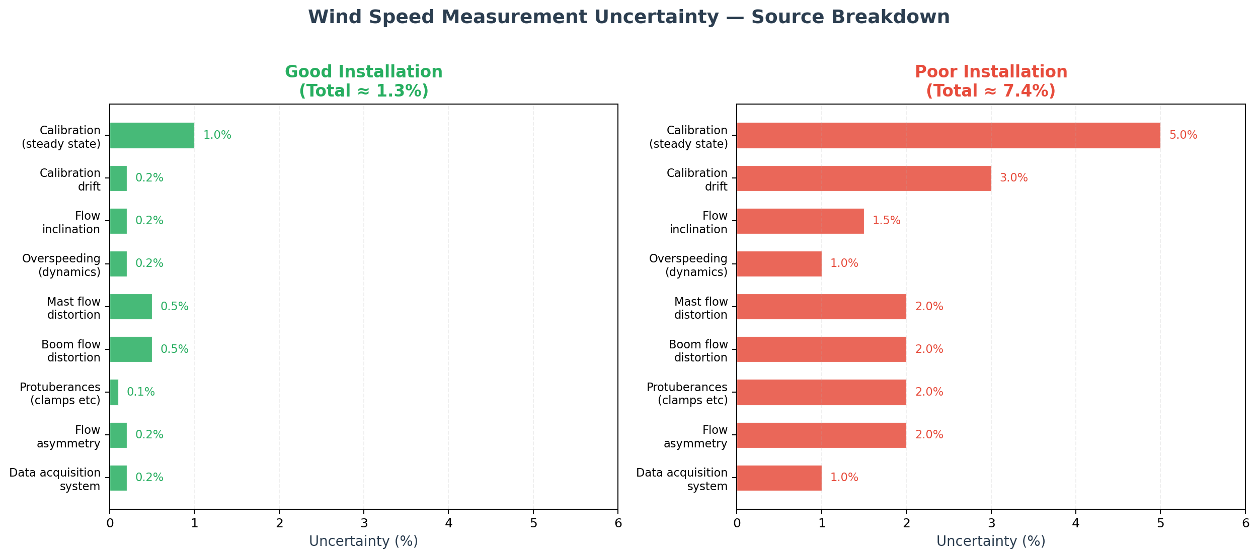
Wind Measurement — What Can Go Wrong
The wind measurement campaign is the foundation of every wind farm project. The instrument at the heart of that campaign — the humble cup anemometer — looks simple, but getting accurate data out of it is anything but. Most of us in the BoP world are not wind resource specialists. We receive the wind assessment…
-
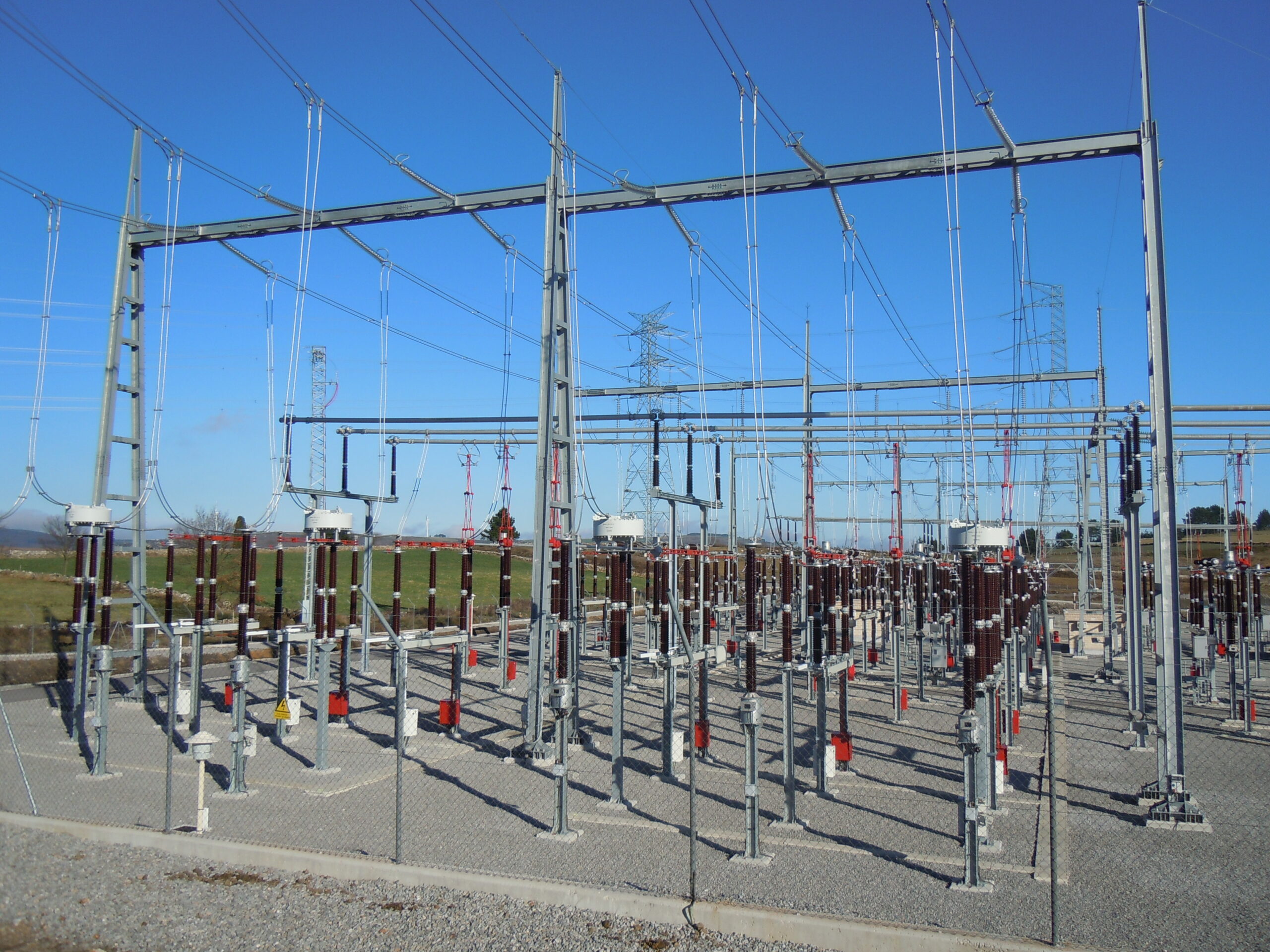
Substation Earthing Design per IEEE 80 — Step by Step
A practical walkthrough of the calculations behind a safe grounding grid, using a real wind farm substation as an example. If you have ever opened a substation earthing calculation and found yourself lost between decrement factors, mesh voltages, and geometric correction coefficients, you are not alone. IEEE Std 80 — the IEEE Guide for Safety…
-
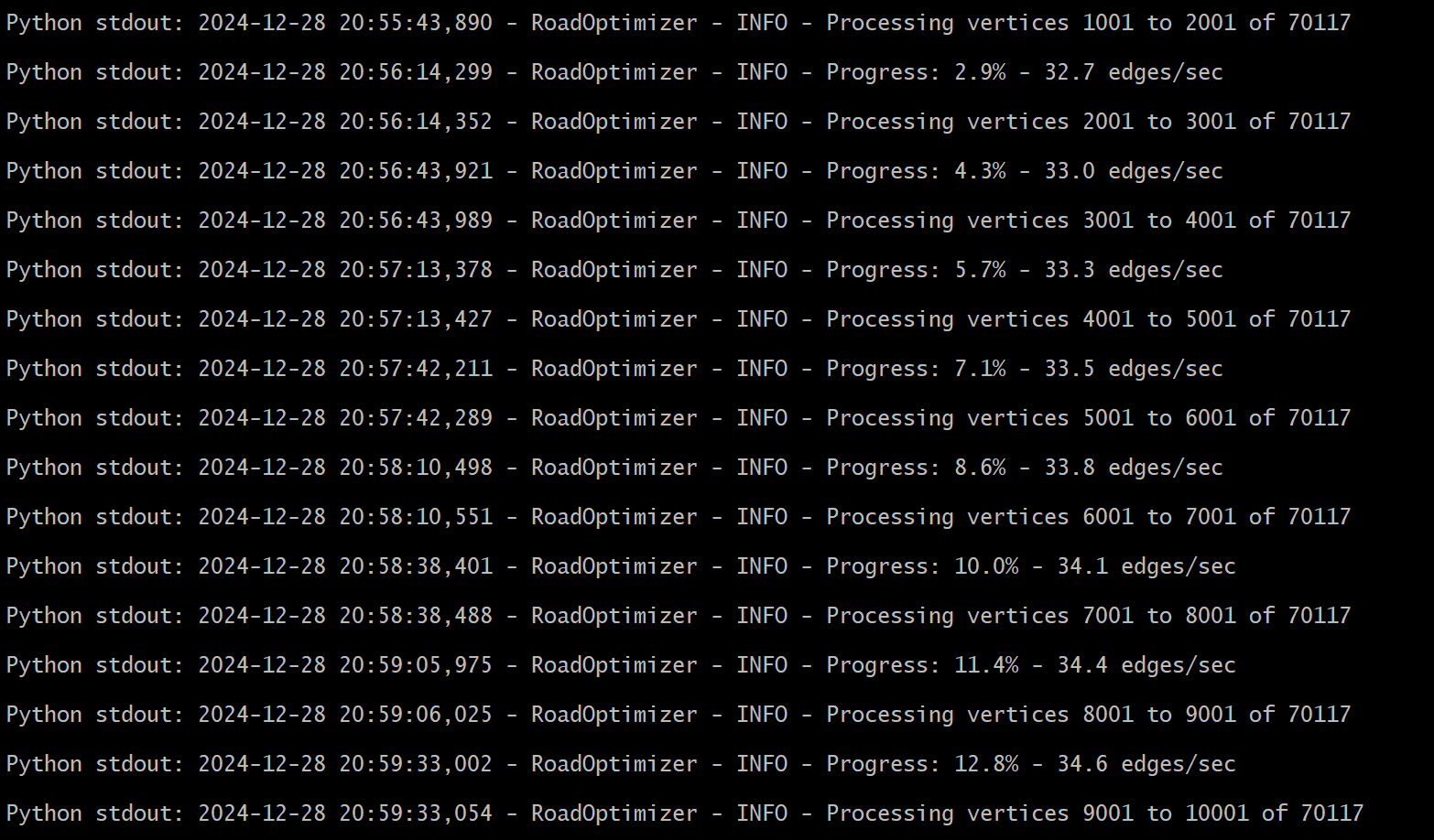
Wind farm internal roads optimization
In parallel with the optimization of crane pads (you can find the article on the topic here) I am also trying to automate the calculation of wind farm internal roads. At the moment I have developed three solutions: the first joins the turbines looking for the minimum spanning tree (MST), i.e., the shortest possible connection….
-
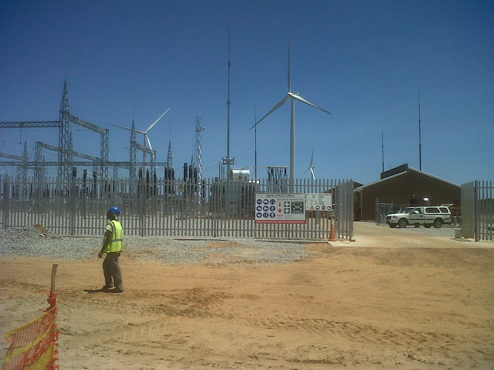
110kV Substation Layout: Single vs Double Busbar Configuration
How to choose the right busbar arrangement for your wind farm? Every onshore wind farm needs a grid connection substation, either an existing or a brand new one. And if you need to build a substation for your wind farm, one of the very first design decisions you’ll face — one that shapes the entire…
-

BoP –> Sourcing
And so, after 15 years of BoP, I decided to start a new chapter and move to Sourcing. I think I will be able to update the blog from time to time thanks to friends and colleagues who are still in BoP. If you happen to have experience in the field and would like to…