
When a gravity foundation cracks, how do you diagnose the problem, design the fix, and execute the repair — all while the turbine stays in place?
Wind turbine foundations are designed to last 25 to 30+ years, matching the operational life of the turbine. They are massive reinforced concrete structures, typically buried several metres underground, carrying cyclic loads from wind, rotor imbalance, and emergency braking events every single day. Most of the time, they perform exactly as designed. But occasionally, something goes wrong.
This post walks through a real foundation repair project — from the initial discovery of cracks, through the structural diagnosis, to the final repair design. The project involved a single turbine position at an operational wind farm in southern Europe, where significant cracking was discovered in the gravity foundation during a routine inspection. The repair was designed by a specialist structural engineering firm and executed without dismantling the turbine.
How a gravity foundation works
Before understanding what went wrong, it helps to understand how these foundations are built in the first place.
A typical onshore wind turbine sits on a gravity foundation — a large, flat, circular or octagonal slab of reinforced concrete, typically 15 to 20+ metres in diameter and 2 to 3 metres deep. The concept is simple: the foundation resists the overturning moment from wind loads through its own weight and the weight of the soil backfilled on top of it. Usually, there are no piles; the foundation simply sits on the bearing soil, relying on a combination of dead weight and base area to keep the overturning stability ratio above the required safety factor.
At the centre of the foundation sits the anchor cage, a steel ring embedded in the concrete, with dozens of high-strength bolts (typically M42 or M48, grade 8.8 or 10.9) protruding vertically from the top surface. These bolts are what connects the steel tower to the concrete foundation. The tower flange sits on the bolts, and each bolt is tensioned to a precise torque value — typically between 2,500 and 3,500+ Nm depending on the turbine model. The interface between the tower base and the foundation top is filled with a high-performance grout that ensures uniform load transfer across the entire contact surface.
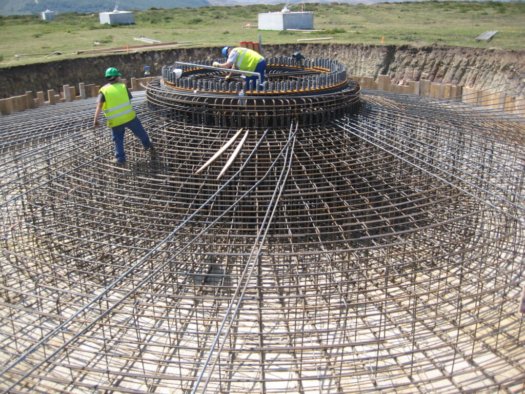
Workers installing the reinforcement cage for a gravity foundation. The circular rebar structure at the centre surround the anchor cage. Note the scale — the excavation is roughly 17 metres across.
The reinforcement is dense. A typical 3MW foundation contains between 25 and 40+ tonnes of steel rebar, arranged in radial and circumferential layers at the top and bottom of the slab, with additional vertical stirrups and shear reinforcement around the pedestal. The concrete is typically C30/37 or C35/45, placed in a single continuous pour that can require 300 to 500 cubic metres — meaning 30 to 50 concrete truck loads arriving in sequence, with the pour lasting 8 to 14 hours.
The point of all this detail is that a gravity foundation is not a simple concrete block. It is a heavily reinforced, precisely engineered structure where the geometry, the reinforcement layout, and the anchor cage alignment all interact. When cracking occurs, the diagnosis is never straightforward.
What happened: discovering the damage
During a scheduled maintenance visit, the site team noticed visible cracks on the exposed top surface of the foundation at a turbine. The cracks were radial — running outward from the central pedestal — and some were wide enough to be clearly visible without magnification.
This kind of finding triggers an immediate investigation. The wind farm operator commissioned a specialist structural engineering firm to perform a pathology study: a systematic diagnosis of the foundation’s condition, the likely causes of the cracking, and a recommendation on whether the foundation could continue in service, needed repair, or needed replacement.
The pathology report documented the following findings. The cracks were concentrated in the upper surface of the foundation slab, radiating outward from the pedestal in a pattern consistent with flexural cracking under cyclic loading. Some cracks extended through the full depth of the slab’s upper concrete cover and showed signs of water ingress — a concern because water reaching the reinforcement bars accelerates corrosion, which in turn causes further cracking as the corroding rebar expands.
The engineers measured crack widths at multiple points. Several cracks exceeded 0.3 mm — the maximum crack width generally accepted by Eurocode 2 (EN 1992-1-1) for reinforced concrete structures exposed to outdoor environments. Above this threshold, the risk of reinforcement corrosion increases significantly because the crack allows moisture, oxygen, and potentially chlorides to reach the steel.
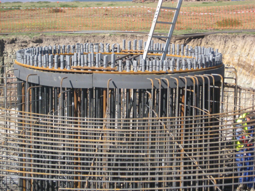
A completed reinforcement cage before concrete pouring. The radial and circumferential rebar layers are clearly visible. Cracking in the finished foundation typically follows the radial reinforcement pattern.
The diagnosis
The pathology report considered several possible causes for the cracking.
Thermal cracking during curing was one hypothesis. Large concrete pours generate significant heat through the exothermic hydration reaction. If the temperature differential between the core and the surface exceeds approximately 20°C, thermal stresses can cause surface cracks during the first days after pouring. However, thermal cracks tend to be shallow and uniformly distributed — not the radial pattern observed here.
Shrinkage cracking was another possibility. Concrete shrinks as it cures and loses moisture, and if the foundation surface dries too quickly (due to wind or sun exposure before adequate curing protection is applied), surface cracks can form. Again, shrinkage cracks tend to be more random and map-like, not radial.
However the most likely cause, according to the engineering analysis, was flexural cracking under operational loads — specifically, the cyclic bending moment transmitted from the tower through the anchor cage into the foundation slab. Every time the wind changes direction or the rotor passes through turbulent zones, the foundation experiences a bending moment that changes in both magnitude and direction. Over millions of load cycles, this can cause fatigue-related cracking, particularly if the original reinforcement was marginally dimensioned for the actual site conditions.
The report also noted that the foundation design dated from an earlier generation of design standards, and that the actual wind conditions at the site may have been more severe than the design assumptions — a situation that is not uncommon in the wind industry, where early projects sometimes used less conservative load assumptions than current practice.
The repair concept
Once the diagnosis confirmed that the foundation could be repaired rather than replaced (replacement would require dismantling the turbine, demolishing the foundation, and building a new one — an operation costing several hundred thousand euros and months of lost production), the engineers designed a structural repair.
The repair concept was straightforward in principle but demanding in execution: strengthen the existing foundation by adding a new reinforced concrete collar around the pedestal area, effectively increasing the cross-section and adding new reinforcement to carry the tensile stresses that had caused the original cracking.
The repair design involved the following sequence of works.
First, excavation. The backfill material covering the foundation had to be removed to expose the full slab surface and the sides of the foundation. This alone is a significant operation — a typical gravity foundation has 2 to 3 metres of compacted soil on top of it, and the excavation must be done carefully to avoid damaging the existing concrete or the underground cable connections that run from the turbine to the collector system.
Second, surface preparation. The cracked concrete surfaces had to be cleaned, and the cracks themselves treated. For cracks wider than 0.3 mm, the specified treatment was epoxy injection — a process where a low-viscosity epoxy resin is injected under pressure into the crack, filling the void and bonding the crack faces together. This restores the watertightness of the concrete and protects the reinforcement from further corrosion. For narrower cracks, a surface-applied sealer was specified.
Third, the new concrete collar. The repair drawings show a new reinforced concrete ring cast around the existing pedestal, tied into the existing foundation with drilled-and-grouted rebar connectors (typically 16 mm or 20 mm diameter bars, drilled into the existing concrete with a rotary hammer and bonded with structural epoxy adhesive like Hilti HIT-RE 500). The new collar increases the effective depth of the foundation in the critical zone around the pedestal, where the bending moments are highest.
Fourth, waterproofing and protection. After the structural repair, the entire exposed surface was waterproofed with a bituminous membrane or polyurethane coating to prevent future water ingress.
Finally, backfill. The excavated material was replaced and compacted in layers, restoring the foundation to its original buried condition.
The structural calculations
The repair design was backed by a full set of structural calculations, following Eurocode 2 (EN 1992-1-1) for reinforced concrete design and the Spanish structural concrete code (EHE-08, Instrucción de Hormigón Estructural).
Several key verifications were done.
The bending capacity of the repaired section was checked against the design overturning moment at the foundation-tower interface. The new reinforcement in the collar was designed to carry the additional tensile force required to bring the section’s moment capacity above the factored design load with an adequate safety margin.
The shear capacity was verified to ensure that the repair collar was adequately connected to the existing foundation. The drilled-and-grouted connectors act as shear dowels, transferring horizontal shear forces across the interface between old and new concrete. The number, diameter, and spacing of these connectors were calculated based on the shear flow at the interface.
The anchorage length of the new reinforcement was checked — every rebar must be embedded deep enough into the concrete (or have adequate hook development) to develop its full tensile strength before it reaches the zone where the stress is needed. This is particularly critical in repair works, where the available space for anchorage is often limited.
Crack width verification was performed for the repaired section under serviceability loads (unfactored loads representing normal operating conditions). The new reinforcement was designed to keep crack widths below 0.3 mm under the maximum expected bending moment — the same criterion that the original foundation had failed to meet.
The calculations also included a check of the bearing pressure under the repaired foundation, confirming that the additional weight of the concrete collar did not exceed the allowable bearing capacity of the soil.
The bill of quantities
The repair project’s measurement document gives a clear picture of the scope of work. For a single turbine foundation repair, the quantities included:
Earthworks: approximately 1,500 cubic metres of excavation to expose the existing foundation, plus the same volume of backfill and compaction after the repair. This required tracked excavators and compaction equipment on site for several days.
Concrete: approximately 15 to 20 cubic metres of new structural concrete (C30/37) for the repair collar — a fraction of the 350+ cubic metres in the original foundation, but requiring the same quality control (slump test, cube samples for 7-day and 28-day compression testing, temperature monitoring).
Reinforcement steel: approximately 2 to 3 tonnes of B500S rebar for the new collar, plus the drilled-and-grouted connectors tying the new concrete to the existing structure.
Formwork: the repair collar requires custom formwork adapted to the existing foundation geometry — this is not standard work and demands experienced formwork carpenters.
Crack injection: epoxy resin injection for all cracks exceeding 0.3 mm width, including the injection ports, sealing paste, and the resin itself.
Waterproofing: bituminous or polyurethane membrane applied to the entire exposed surface after repair.
Lessons for design and construction
This case study illustrates several important points that anyone involved in wind farm foundation design or construction should keep in mind.
The first is that foundation cracking in wind turbines is not unusual, and it does not always mean the foundation has failed. Reinforced concrete is designed to crack — the reinforcement is there precisely to carry tensile stresses across the cracks. The question is always whether the cracks are within acceptable limits (width, depth, pattern) or whether they indicate a structural problem that requires intervention.
The second lesson is the critical importance of the curing process. Many foundation pathologies can be traced back to inadequate curing protection during the first 7 to 14 days after the concrete pour. Covering the fresh concrete with curing blankets or curing compound, controlling the temperature differential, and avoiding premature loading are not optional extras — they are essential steps that directly affect the long-term durability of the structure.
The third point is about design conservatism. Wind turbine loads are cyclic and highly variable, and the actual wind conditions at a site may differ from the design assumptions. A foundation that is marginally adequate under the design loads may develop problems under slightly different real-world conditions. Modern design practice tends to apply more conservative fatigue load factors than earlier generations, partly as a result of cases like the one described here.
Finally, this case demonstrates the value of periodic foundation inspections. Once a foundation is backfilled, the concrete slab is invisible. Cracks can develop and propagate for years without anyone knowing. Some operators now include foundation inspections in their long-term maintenance plans — either by partial excavation of selected foundations, or by installing monitoring systems (strain gauges, tilt sensors, or fibre optic cables embedded in the concrete) that can detect changes in the foundation’s structural behaviour without digging it up.
The grouting interface
One area that deserves special attention — both in original construction and in repair situations — is the grout layer between the foundation top and the tower base flange. This thin layer (typically 20 to 50 mm thick) must transfer the full compression and shear from the tower into the foundation, while accommodating small imperfections in the concrete surface.
The grouting operation is typically performed just before or just after the first tower section is erected, and it requires careful preparation: the concrete surface must be roughened and wetted, the formwork must be sealed to prevent leakage, and the grout must be mixed to the exact water ratio specified by the manufacturer. Too much water weakens the grout; too little makes it impossible to pour. The mixing is often done at night to avoid high temperatures that accelerate setting.
In a repair scenario, the grout interface may need to be inspected and potentially replaced if the cracking has affected the pedestal area directly beneath the tower. This adds considerable complexity to the repair, because the tower cannot be unloaded from the foundation while the grout is being replaced — the turbine remains in place throughout.
Key takeaways
Wind turbine gravity foundations are robust structures, but they are not immune to damage. Cracking can occur due to thermal effects during curing, inadequate reinforcement for the actual load conditions, or simply the relentless accumulation of millions of load cycles over years of operation.
When cracking is discovered, the response should be systematic: document the damage, commission a specialist pathology study, design a repair based on structural calculations, and execute the works with the same quality standards as a new foundation. The repair option — adding a reinforced concrete collar and injecting the existing cracks — is typically far more economical than replacement, provided the damage has not progressed too far.
For new projects, the lessons are clear. Invest in proper curing protection, apply conservative design margins for fatigue loads, and plan for periodic inspections that allow the foundation’s condition to be assessed over time. The foundation is the one part of a wind turbine that cannot be replaced without dismantling everything above it — which makes getting it right the first time not just good engineering, but good economics.
Leave a Reply