A practical walkthrough of the calculations behind a safe grounding grid, using a real wind farm substation as an example.
If you have ever opened a substation earthing calculation and found yourself lost between decrement factors, mesh voltages, and geometric correction coefficients, you are not alone. IEEE Std 80 — the IEEE Guide for Safety in AC Substation Grounding — is one of those standards that is thorough to the point of being intimidating. It covers everything from soil resistivity measurement techniques to the physiology of electric shock, and the design procedure involves a chain of interdependent equations that can feel circular until you see them applied to a real case.
This post walks through the full IEEE 80 design process, step by step, using actual input data from a 110 kV wind farm substation. The goal is not to replace the standard — you still need IEEE 80 on your desk — but to make the calculation sequence understandable by showing how each parameter feeds into the next, and where the engineering judgement comes in.
Why earthing design matters
The purpose of a substation grounding system is simple to state and demanding to achieve: ensure that no person inside or near the substation can be exposed to a dangerous electric shock during a ground fault. A ground fault drives thousands of amperes into the earth through the grounding grid, and this current creates voltage gradients across the soil surface. If a person is standing on the ground and touching a grounded structure (a fence, an equipment frame, a steel column), the voltage difference between their hand and their feet — the touch voltage — can push a lethal current through their body. Similarly, a person simply walking across the soil surface can be exposed to a voltage difference between their two feet — the step voltage.
The earthing design must keep both of these voltages below tolerable limits that depend on the fault duration, the surface material, and the assumed body weight of the person. IEEE 80 provides the equations, the material constants, and the design procedure to verify this. The entire calculation boils down to one question: for a given fault current, soil resistivity, and grid geometry, are the calculated touch and step voltages lower than the tolerable limits?

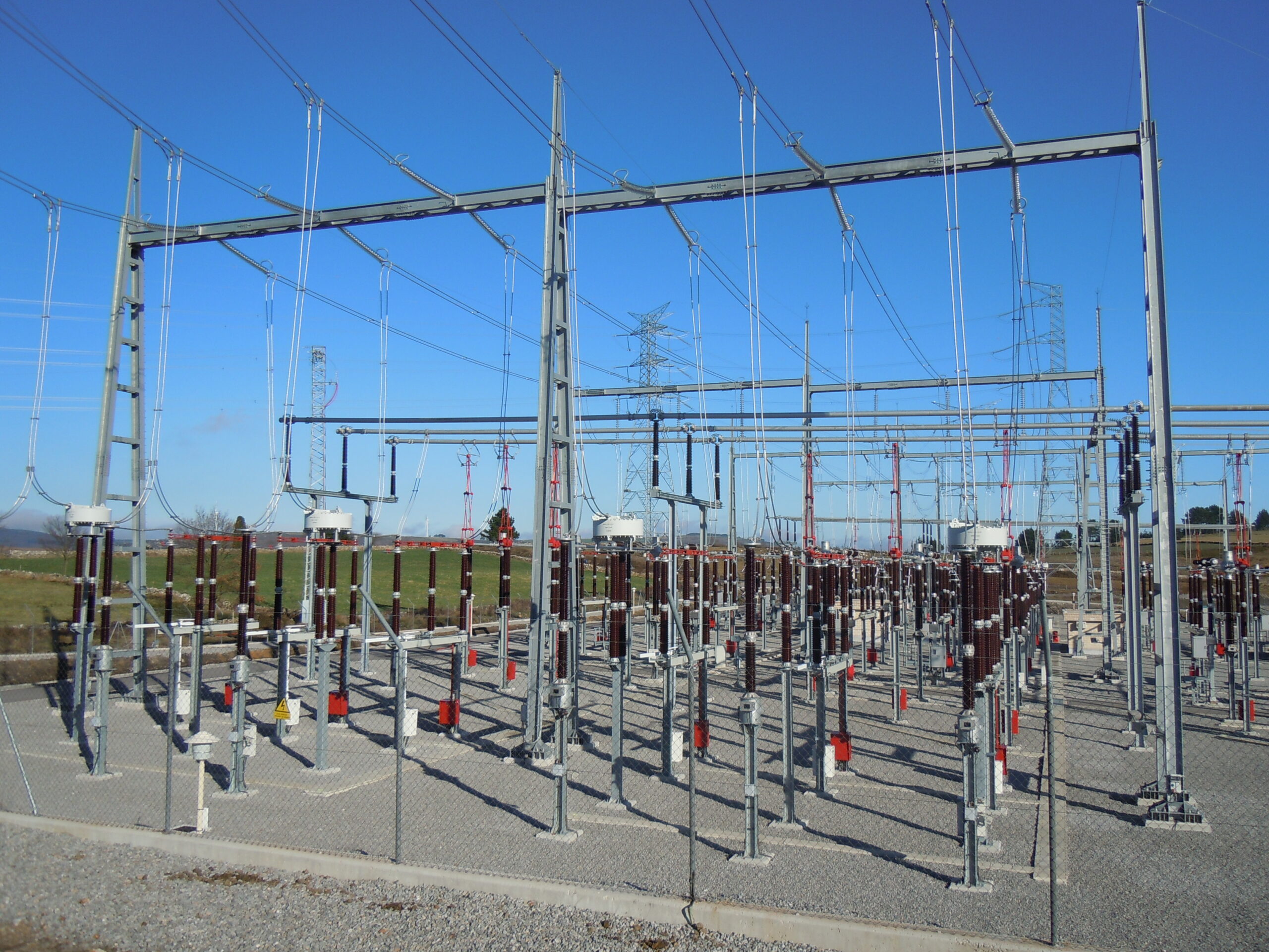
A 110 kV substation switchyard. The crushed gravel surface layer is not just for drainage — it plays a critical role in the earthing design by increasing the contact resistance between a person’s feet and the native soil, which raises the tolerable touch and step voltage thresholds.
The inputs you need before you start
Before opening a spreadsheet, you need to collect several categories of input data. Some come from the electrical system design, some from geotechnical investigations, and some from the physical layout of the substation.
The first category is the grounding grid geometry. You need the dimensions of the area to be covered by the grid — typically the full switchyard perimeter. For a wind farm substation this might be a rectangle of roughly 40 by 65 metres, though the exact size depends on the busbar configuration, the number of bays, and the clearances defined by IEC 61936. Within this rectangle, you need the spacing between parallel conductors (typically 4 to 7 metres) and the burial depth (usually 0.5 to 0.8 metres). You also need to decide on the number and length of vertical ground rods — driven copper-clad steel rods, typically 3 metres long, placed at the grid perimeter and at key equipment locations.
The second category is the soil data. The single most important parameter in the entire calculation is the soil resistivity, ρ, measured in ohm-metres. This comes from a geotechnical investigation using the Wenner four-pin method or driven-rod measurements. Soil resistivity varies enormously — from 10 Ω·m for wet clay to over 10,000 Ω·m for dry rock. A typical value for a wind farm site in southern Europe might be 50 to 150 Ω·m. You also need the resistivity of the surface layer material, ρs. Crushed rock or gravel has a resistivity of 2,000 to 10,000 Ω·m (IEEE 80 Table 7 gives 3,000 Ω·m for washed gravel and up to 6,000 Ω·m for specific types), and a typical design value is 3,000 to 5,000 Ω·m. The thickness of this surface layer, hs, is normally 0.1 to 0.2 metres.
The third category is the electrical system data. You need the maximum ground fault current (3I₀), the fault duration for conductor sizing (tc, typically 1 second), the shock duration for touch and step voltage evaluation (ts, typically 0.5 seconds — corresponding to the backup protection clearing time), the system frequency (50 or 60 Hz), and the system X/R ratio at the fault point.
Step 1: Conductor sizing
The first calculation has nothing to do with touch or step voltages — it is about making sure the grounding conductors themselves survive the fault without melting. IEEE 80 Equation 37 gives the minimum conductor cross-section based on the fault current, the fault duration, and the thermal properties of the conductor material:
A = I × √(tc) / K
where K is a material-dependent constant that accounts for the thermal capacity, resistivity, and maximum allowable temperature of the conductor. For annealed soft-drawn copper (the most common grounding conductor material), the relevant constants from IEEE 80 Table 1 are: thermal coefficient of resistivity αr = 0.00393 /°C, resistivity ρr = 1.72 μΩ·cm, thermal capacity factor TCAP = 3.42 J/cm³/°C, and maximum allowable temperature Tm = 1,083 °C (the melting point of copper).
In practice, you need to size two types of conductors separately. The riser conductors — the vertical connections from each piece of equipment down to the grid — carry the full fault current, so they are sized for the worst-case 3I₀. In our example, with a maximum fault current of 31.5 kA and a 1-second duration, the minimum riser cross-section comes out to about 113 mm². The chosen size is 120 mm² (a standard bare copper conductor size).
The main grid conductors carry only a fraction of the fault current, because the current divides between multiple parallel paths. IEEE 80 Section 11.3.3 discusses this: a common assumption is that 60% of the fault current flows through the grid conductor at any given point (the “current division factor”). With this factor applied, the grid conductor minimum is about 68 mm², and the chosen size is 95 mm² — providing a comfortable margin.
Step 2: Tolerable touch and step voltages
This is where the safety criteria are established. IEEE 80 defines tolerable voltages based on the assumption that the human body has a resistance of 1,000 Ω (hand-to-feet or foot-to-foot), and that the contact resistance of the feet with the ground depends on the surface material.
The key concept here is the surface layer derating factor, Cs. Because the substation surface is covered with crushed gravel (high resistivity), the resistance between a person’s feet and the native soil is much higher than if they were standing on bare earth. This effectively limits the current that can flow through the body for a given voltage. Cs is calculated from IEEE 80 Equation 27:
Cs = 1 − 0.09 × (1 − ρ/ρs) / (2hs + 0.09)
With ρ = 75 Ω·m, ρs = 4,000 Ω·m, and hs = 0.2 m, Cs comes out to approximately 0.82. This factor then enters the tolerable voltage equations.
For a 70 kg person (IEEE 80 Equations 30 and 33):
Tolerable step voltage = (1,000 + 6 × Cs × ρs) × 0.157 / √ts
Tolerable touch voltage = (1,000 + 1.5 × Cs × ρs) × 0.157 / √ts
Notice the asymmetry: the step voltage formula uses 6 × Cs × ρs because the current path is foot-to-foot (two feet in series with the soil), while the touch voltage formula uses 1.5 × Cs × ρs because the current path is hand-to-feet (one hand to two parallel feet). This is why the tolerable step voltage is always much higher than the tolerable touch voltage — in our example, about 4,590 V versus 1,314 V for ts = 0.5 seconds.
In most practical cases, touch voltage is the governing criterion, although step voltage may govern in large or sparsely spaced grids.
Step 3: Grid resistance
The grounding grid resistance determines how much the entire grid potential rises above true earth during a fault. IEEE 80 Equation 52 gives a simplified formula for the resistance of a grid with ground rods:
Rg = ρ × { 1/LT + 1/√(20·A) × [1 + 1/(1 + h×√(20/A))] }
where LT is the total length of all buried conductors (horizontal grid plus vertical rods), A is the area enclosed by the grid, and h is the burial depth. In our example, with 1,156 metres of horizontal conductor, 90 metres of ground rods (30 rods × 3 m each), a grid area of 2,855 m², and ρ = 75 Ω·m, the calculated grid resistance is approximately 0.67 Ω.
This is a reasonable value for a substation of this size. Grid resistance below 1 Ω is generally considered good practice, though IEEE 80 does not set a specific limit — the real acceptance criterion is the touch and step voltage comparison, not the absolute resistance value. That said, many utilities and grid codes specify a maximum ground resistance (often 1 Ω or 5 Ω depending on the voltage level), so this parameter is worth tracking.
Step 4: Maximum grid current and GPR
Not all of the fault current flows through the grounding grid and into the earth. A significant portion returns to the source through the overhead ground wires (OHGW) of the transmission lines connected to the substation, bypassing the grid entirely. IEEE 80 uses a split factor to account for this: typically 40% to 70% of the fault current flows through the grid, depending on the number and impedance of the connected lines.
In our example, the assumption is that 60% of the fault current from the remote source returns through the ground (the rest via the overhead ground wires). With a remote-source fault current of 17 kA (3I₀’), this gives a symmetrical grid current Ig of 10.2 kA. After applying the decrement factor Df (which accounts for the asymmetric DC offset in the first cycles of the fault), the maximum grid current IG becomes approximately 10.7 kA.
The Ground Potential Rise (GPR) is simply the product of the maximum grid current and the grid resistance:
GPR = IG × Rg = 10,676 × 0.668 ≈ 7,134 V
This is the voltage that the entire grounding grid rises to, relative to a remote earth reference, during the fault. If the GPR is lower than the tolerable touch voltage, no further analysis is needed — the design is safe by definition. In our case, the GPR of 7,134 V is well above the tolerable touch voltage of 1,314 V, so we must proceed to calculate the actual mesh and step voltages and verify that they are within limits.
Step 5: Mesh voltage (the critical check)
The mesh voltage Em is the maximum touch voltage that occurs at the centre of the worst-case mesh — typically a corner mesh of the grid, where the current density is highest and the voltage gradient is steepest. This is the value that must be compared against the tolerable touch voltage.
The mesh voltage calculation is where IEEE 80 gets algebraically intense, but the structure is straightforward. It combines three factors: a geometric factor Km that depends on the grid spacing, depth, and conductor diameter; a correction factor Ki that accounts for the irregularity of current distribution; and the maximum grid current divided by the effective conductor length.
The geometric factor Km (IEEE 80 Equation 81) is a logarithmic expression that captures the effect of conductor spacing D, burial depth h, conductor diameter d, and a correction for grids with ground rods. For our example (D ≈ 5.45 m, h = 0.8 m, d = 0.0124 m, with ground rods along the perimeter), Km comes out to approximately 0.64.
The correction factor Ki (IEEE 80 Equation 89) depends on the equivalent number of parallel conductors n, which is itself calculated from the grid geometry using the na, nb, nc, nd coefficients. For a rectangular grid with Lx = 43.75 m, Ly = 65.25 m, and 1,156 m of horizontal conductor, n ≈ 10.7 and Ki ≈ 2.23.
The effective buried length LM for mesh voltage (IEEE 80 Equation 91) accounts for the contribution of ground rods, and in our case comes to approximately 1,300 m.
The mesh voltage is then:
Em = ρ × Km × Ki × IG / LM = 75 × 0.64 × 2.23 × 10,676 / 1,300 ≈ 880 V
This is the critical comparison: the calculated mesh voltage of 880 V is below the tolerable touch voltage of 1,314 V. The design passes.
Step 6: Step voltage verification
The step voltage calculation follows a similar pattern but uses different geometric and length factors. The spacing factor Ks (IEEE 80 Equation 94) and the effective buried length Ls (IEEE 80 Equation 93) are both specific to the step voltage case:
Es = ρ × Ks × Ki × IG / Ls = 75 × 0.308 × 2.23 × 10,676 / 943.5 ≈ 583 V
Compared to the tolerable step voltage of 4,590 V, this is comfortably within limits — as expected, since touch voltage is always the governing criterion.
The summary table
At the end of the calculation, the results are typically presented as a comparison table:
| Parameter | Tolerable (70 kg) | Calculated | Ratio |
|---|---|---|---|
| Touch voltage | 1,314 V | 880 V | 67% |
| Step voltage | 4,590 V | 583 V | 13% |
Both calculated values are below the tolerable limits, confirming that the grounding system design is safe for personnel. The touch voltage ratio of 67% indicates a reasonable margin — not so tight that small changes in soil resistivity would push it over the limit, but not so generous that the grid is over-designed.
The calculation also produces several design outputs that feed into the construction drawings and specifications:
The riser conductor size (120 mm² bare copper), the main grid conductor size (95 mm² bare copper), the total length of horizontal conductor (1,156 m), the number and length of ground rods (30 rods × 3 m), and the calculated grid resistance (0.67 Ω).
What the numbers don’t tell you
The IEEE 80 calculation is a necessary part of the design, but it is not sufficient on its own. Several practical considerations require engineering judgement beyond the equations.
Soil resistivity is never uniform. The calculation assumes a homogeneous soil model (or at most a two-layer model), but real soils are heterogeneous — resistivity can vary by an order of magnitude across the substation footprint, and it changes with moisture content and temperature throughout the year. The design should be checked against a range of resistivity values, not just the average measurement, and a conservative approach is to use the highest measured value for the touch voltage verification and the lowest for the grid resistance check.
The grid layout must be coordinated with the civil works. The grounding conductors share the same underground space as foundations, cable trenches, drainage pipes, and earthing of individual equipment. The IEEE 80 calculation assumes a regular rectangular grid with uniform spacing, but the actual as-built layout will have irregularities around foundations and trenches. The spacing D used in the calculation should reflect the worst-case mesh, not the average.
Connections matter as much as the grid itself. IEEE 80 specifies that all connections in the grounding network should be made by exothermic welding (Cadweld or equivalent) rather than mechanical clamps, because exothermic welds provide a molecular bond that does not degrade over time. A single high-resistance connection can create a dangerous voltage gradient that the calculation does not account for.
The surface layer must actually be there. The entire tolerable voltage calculation relies on the assumption that a 150–200 mm layer of crushed gravel covers the substation surface. If this layer is missing, contaminated with fine soil, or too thin, the tolerable voltages drop dramatically — in our example, removing the gravel layer would reduce the tolerable touch voltage from 1,314 V to about 222 V, well below the calculated mesh voltage of 880 V. Maintaining the gravel layer is an operational requirement, not just a construction detail.
A note on software
Many engineers use specialized software (such as ETAP, CDEGS, or AutoGrid Pro) to perform grounding grid analysis, particularly for complex geometries, non-uniform soils, or substations with multiple interconnected grids. These tools use finite element methods or boundary element methods to compute the actual potential distribution across the grid surface, producing detailed contour plots of touch and step voltages rather than single worst-case values.
However, even when using software, it is valuable to understand the manual IEEE 80 calculation. The hand calculation provides a sanity check on the software output, helps you understand which parameters drive the result, and is often sufficient for the preliminary design stage — saving the detailed modelling for final verification. The spreadsheet-based approach shown in this post is how most wind farm substation earthing designs begin, and for many projects it is all that is needed.
Key references
The primary reference is IEEE Std 80-2000 (or the 2013 revision, IEEE Std 80-2013), “IEEE Guide for Safety in AC Substation Grounding.” The equations referenced in this post use the 2000 edition numbering. Other relevant standards include IEEE Std 81 (for soil resistivity measurement procedures), IEC 61936-1 (which covers earthing requirements for power installations above 1 kV as part of the broader substation design standard), and IEC 60364-5-54 (for earthing arrangements and protective conductors in low-voltage installations within the substation).
For wind farm-specific earthing guidance, IEC 61400-24 covers lightning protection and earthing systems for wind turbines, and turbine manufacturers (Vestas, Siemens Gamesa, etc.) typically provide their own earthing system specifications for the foundation and tower, which must be integrated with the substation and collector system grounding.
The calculation example in this post is based on a real 110 kV wind farm substation design. Input parameters have been kept as-is to show realistic values, but the project name and location have been omitted.
Leave a Reply