A practical look at why capacitor banks end up in every wind farm substation, and what you need to understand about reactive energy compensation to specify them correctly.
If you have been involved in the electrical design of a wind farm substation, maybe you have seen a capacitor bank in the single line diagram. It is one of those items that sits quietly in the corner of the substation building (or in its own outdoor enclosure), does not move, makes no noise, and rarely gets discussed in project meetings — until the grid operator starts asking questions about your power factor at the point of common coupling.
In this post I will try to explain what reactive energy is, why it matters for wind farms, and how the compensation equipment is specified and sized. The topic is well covered in electrical engineering textbooks, but I have found that many of us coming from a civil background (myself included) tend to gloss over it. That is a mistake, because the capacitor bank are a real cost item in the substation, and getting the sizing wrong can lead to penalties from the grid operator or, in extreme cases, to equipment damage.
The Power Triangle — A Quick Refresher
Every AC electrical system deals with three types of power. Active power (P), measured in kW, is the useful power that does actual work — it turns motors, heats resistors, lights lamps. Reactive power (Q), measured in kVAr, is the power that oscillates back and forth between the source and the load to sustain the magnetic fields in transformers, motors, and inductors. It does no useful work, but without it the equipment cannot function. And apparent power (S), measured in kVA, is the vector sum of the two: S = sqrt(P² + Q²).
These three quantities form a right triangle — the power triangle. The angle between the active power (the horizontal side) and the apparent power (the hypotenuse) is called phi (φ), and the cosine of that angle is the power factor: cos φ = P / S.
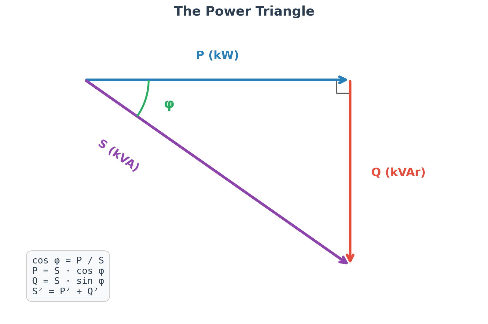
A purely resistive load (a heater, for instance) has cos φ = 1 — all the power drawn from the grid is active power, and S equals P. A pure inductor has cos φ = 0 — it draws current but produces no useful work. Real industrial loads fall somewhere in between. A typical induction motor at full load has a power factor of around 0.85, dropping to 0.70 or lower at partial load. Transformers at no-load can be even worse. Fluorescent lighting, welding equipment, variable speed drives — all of these pull the power factor down.
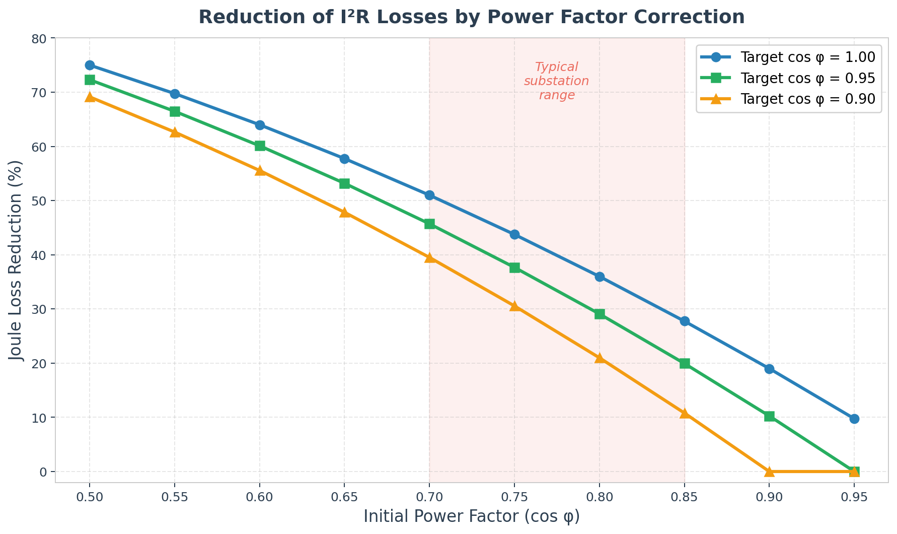
The practical consequence is this: for a given amount of useful work (P), a low power factor means the grid has to deliver a higher total current to the installation. That higher current causes larger I²R losses in the cables, bigger voltage drops, and requires the transformers and generators upstream to be rated for a higher apparent power than the active load actually needs.
Why It Matters for Wind Farms
You might think that a wind farm, being a generator rather than a consumer, does not have the same reactive energy concerns as an industrial plant. That is only partly true.
A wind farm substation contains power transformers (the main step-up transformer from 33 kV to 110 kV or 220 kV, plus the auxiliary transformer), motors for cooling fans and pumps, lighting, HVAC systems, and various control and communication equipment. All of these are loads, and most of them are inductive. The main transformer alone, when operating at partial load (which is most of the time in a wind farm), absorbs a significant amount of reactive power.
On top of the substation loads, the grid code in most countries requires the wind farm to maintain its power factor within a specified band at the point of common coupling — typically between 0.95 inductive and 0.95 capacitive, though the exact requirements vary by country and grid operator. The turbines themselves can provide some reactive power compensation through their converters, but the substation auxiliaries and the transformer reactive losses still need to be dealt with locally.
This is where the capacitor bank comes in. By installing capacitors that generate reactive power in the opposite direction to the inductive loads, you reduce the net reactive power drawn from the grid, bring the power factor closer to unity, and avoid penalties.
How Capacitor Banks Work
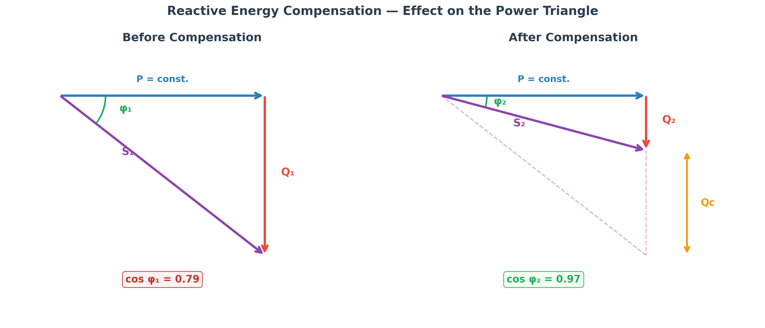
The principle is straightforward. A capacitor generates reactive power of the capacitive type (leading current), which is exactly opposite to the inductive reactive power consumed by transformers and motors. When you connect a capacitor bank in parallel with an inductive load, the reactive current circulates locally between the capacitor and the inductor, and the grid only has to supply the active power plus whatever residual reactive power remains after compensation.
The amount of capacitive reactive power needed is calculated from the power triangle. If your installation has an active power P (in kW), an initial power factor cos φ₁, and you want to reach a target power factor cos φ₂, the required capacitor bank rating is:
Q_c = P × (tan φ₁ − tan φ₂)
For example, if you have an installation consuming 450 kW at a power factor of 0.75 and you want to bring it up to 0.95, you would need Q_c = 450 × (tan(acos(0.75)) − tan(acos(0.95))) = 450 × (0.882 − 0.329) = 450 × 0.553 ≈ 249 kVAr. You would round up to the nearest commercial size — probably a 250 kVAr bank.
In practice, most manufacturers publish lookup tables that give the multiplying factor (often called “k”) directly for each combination of initial and target cos φ, so you do not need to compute tangents every time.
Compensation Strategies — Where to Put the Capacitors
There are three main approaches to reactive energy compensation, and the choice depends on the nature of the installation.
Individual compensation means placing a capacitor directly at the terminals of each large inductive load — typically a motor or a transformer. The reactive current stays confined between the capacitor and the load, so the cables feeding that load carry less current and can be smaller. This approach is ideal when you have a few large, continuously running loads. The downside is cost: you need a separate capacitor (and its protection) for each load, and if the load is switched off the capacitor sits idle.
There is an important caveat with individual motor compensation. If the capacitor remains connected to the motor terminals when the motor is switched off, the motor’s inertia keeps it spinning for a few seconds, and the capacitor can excite the motor’s residual magnetic field, causing it to act as a generator and produce dangerous overvoltages at its terminals. This phenomenon is called auto-excitation, and to prevent it the capacitor rating should never exceed about 90% of the motor’s no-load reactive power consumption (some standards say the capacitor should not exceed 30% of the motor’s rated active power as a practical rule of thumb). Alternatively, the capacitor can be connected through a contactor so it is disconnected whenever the motor is switched off.
Group compensation places a capacitor bank at the distribution board feeding a group of loads that operate simultaneously. This is a good compromise when the loads have similar duty cycles.
Centralised compensation — the most common approach in substations — places a single capacitor bank at the main low voltage switchboard or at the medium voltage busbar. The bank is usually divided into several steps (stages) that are switched in and out automatically by a power factor controller (also called a varimetric relay or a cos φ regulator). The controller continuously monitors the power factor at the point of measurement and connects or disconnects capacitor steps to keep the power factor within the target band.
In a wind farm substation, you will almost always see centralised compensation for the LV auxiliary loads, and sometimes an additional MV capacitor bank on the main busbar if the grid code requirements demand it.
Fixed vs Automatic Compensation
A fixed capacitor bank is the simplest solution: a set of capacitors permanently connected to the busbar, providing a constant amount of reactive power. This works well when the load is stable and predictable — for example, compensating the no-load reactive power of a transformer that runs 24/7.
An automatic bank is divided into steps that are switched by a controller. The controller measures the cos φ in real time and adds or removes steps to match the changing load. This is essential when the load profile varies throughout the day (which is the case in most real installations, and certainly in a wind farm substation where the auxiliary loads depend on how many turbines are running and whether cooling systems are active).
The step sizing matters. If you need an 80 kVAr bank and you split it into equal steps of 20 kVAr (ratio 1:1:1:1), the controller can only produce 0, 20, 40, 60, or 80 kVAr — five discrete levels. That might not be fine-grained enough. A better approach is to use steps in a 1:2:4 ratio — for example, one step of 5 kVAr, one of 10 kVAr, and three of 20 kVAr — which gives many more possible combinations and allows the controller to track the load more closely with fewer switching operations. The 1:1:2:4:4 ratio is particularly common in commercial automatic banks.
Transformer Reactive Power — Often Underestimated
One thing I have noticed is that the reactive power consumed by transformers gets overlooked in the initial design. A transformer absorbs reactive power in two ways: the no-load (magnetising) component, which is constant regardless of the load, and the load-dependent component, which increases with the square of the loading.
The total reactive power of a transformer can be approximated as:
Q_transformer = Q₀ + (u_k / 100) × (S / S_n)² × S_n
where Q₀ is the no-load reactive power, u_k is the short-circuit voltage in percent (typically 6–10% for MV/LV transformers), S is the actual apparent power, and S_n is the rated apparent power.
For a rough sizing, a practical approximation is to compensate with Q ≈ 0.05 × S_n for transformers up to 1,000 kVA, and Q ≈ 0.03 × S_n for larger units. This only covers the no-load reactive power — if the transformer regularly operates at significant load, you will need more.
In a wind farm substation with a 630 kVA auxiliary transformer, this means you should budget at least 30–40 kVAr of compensation just for the transformer, before even considering the motors and other loads.
Harmonics — The Hidden Complication
If your installation has variable speed drives (which a modern wind farm substation certainly does — for cooling fans, pumps, and possibly HVAC), you need to think about harmonics before specifying capacitor banks.
Variable speed drives, rectifiers, and UPS systems generate harmonic currents — currents at multiples of the fundamental frequency (150 Hz, 250 Hz, 350 Hz for the 3rd, 5th, and 7th harmonics at 50 Hz). The problem is that a capacitor’s impedance decreases with frequency (X_c = 1 / (2πfC)), so it presents a low-impedance path for harmonic currents. The capacitor effectively absorbs harmonics from the network, which causes overheating and can damage the dielectric.
Worse, the capacitor bank and the network inductance (mainly the transformer’s leakage inductance) form a resonant circuit. The resonant frequency is h = sqrt(S_cc / Q_c), where S_cc is the short-circuit power at the connection point and Q_c is the capacitor bank rating. If this resonant frequency coincides with one of the harmonic frequencies present in the installation, the resonance amplifies the harmonic voltages and currents dramatically, and the capacitor bank can be destroyed.
The practical solution is to use detuned reactors (also called anti-resonance reactors) in series with the capacitors. These shift the resonant frequency below the lowest significant harmonic (typically below the 3rd or 5th harmonic) and prevent resonance. In installations with significant harmonic content, you should always specify capacitors rated for harmonic environments — look for the Gh/Sn classification in the manufacturer’s catalogue, which indicates the permissible harmonic content.
Practical Sizing for a Wind Farm Substation
The sizing process in a real project follows these steps. First, you list all the loads in the substation — auxiliary transformer, cooling fans, oil pumps, HVAC, lighting, control room equipment — and estimate their active power and power factor. Second, you calculate the total reactive power consumed and the overall power factor. Third, you determine the target power factor (from the grid code or the client’s specification). Fourth, you apply the Q_c = P × (tan φ₁ − tan φ₂) formula to find the required compensation. Fifth, you add a margin of 15–20% for future expansions (this is standard practice). And sixth, you check the harmonic environment and specify detuned reactors if necessary.
For the switchgear protecting the capacitor bank, remember that IEC 60831 requires capacitors to withstand a permanent overcurrent of 30% above their rated current (to account for harmonic content and voltage variations). This means the circuit breaker should be rated at 1.36 times the nominal capacitor bank current, the fuses at 1.6 times, and the cables at 1.3 times the nominal current (some references say 1.8 times for cables, to be safe).
The contactors in an automatic bank need to be specifically designed for capacitor switching. The inrush current when energising a capacitor step can reach 30 times the nominal current for individual compensation and up to 180–200 times the nominal current when other capacitor steps are already energised. Standard contactors will not survive this — you need contactors with pre-insertion resistors that limit the inrush.
Standards
The main reference standards for power capacitors are IEC 60831 (low voltage self-healing capacitors) and IEC 60871 (high voltage shunt capacitors). The capacitors should be of the dry, self-healing type — meaning that if a small dielectric puncture occurs, the metallised film around the puncture evaporates and the capacitor continues to operate, rather than failing catastrophically. Modern capacitor units also include discharge resistors (which reduce the terminal voltage to below 75 V within 3 minutes of disconnection, per IEC 60831), internal fuses, and overpressure disconnection devices.
For the power factor controller, the Schneider Electric Varlogic family (NR6, NR12, NRC12) is widely used, and other manufacturers like ABB, Circutor, and RTR Energía offer equivalent products. The controller should have at least 6 steps (12 is better for fine-grained control), auto-programming capability, and ideally RS-485 Modbus communication for integration with the SCADA system.
A Note on the BoP Context
From a BoP perspective, the capacitor bank is part of the substation electrical design, and it is typically specified in the substation contract. But I have seen cases where the BoP contractor assumed the turbine supplier would handle all reactive compensation through the turbine converters, and the turbine supplier assumed the substation would have a capacitor bank for the auxiliary loads. The result was a gap that only surfaced during commissioning, when the grid operator flagged the power factor at the point of common coupling.
The lesson is simple: make sure the reactive compensation responsibility is clearly allocated in the interface document between the turbine supply contract and the BoP contract. Specify who compensates what, at which voltage level, and to what target power factor. It is one of those interface items that costs very little to get right upfront and can be surprisingly expensive to fix later.
Leave a Reply