The small layer that carries the full weight of a wind turbine — and why getting it wrong can be catastrophic.
There is a thin layer of material between the steel tower of a wind turbine and the concrete foundation it sits on. It is typically 20 to 50 millimetres thick, it weighs less than a tonne, and it takes a few hours to install. Yet this layer — the grout — is responsible for transferring every newton of force from the tower into the foundation: the dead weight of the nacelle and rotor, the bending moment from wind loads, the dynamic forces from emergency stops, and the cyclic fatigue from millions of load reversals over the turbine’s 25-year design life.
If the grout is done well, nobody ever thinks about it again. If it is done badly — wrong mix, air voids, poor surface preparation, grouting in the wrong temperature — the consequences range from localised cracking and water ingress to a complete loss of load transfer that can require dismantling the turbine to repair. I have seen both outcomes, and the difference almost always comes down to the care taken during a single night’s work.
This post covers the materials, the process, and the quality controls involved in grouting a wind turbine tower-foundation interface, based on real project experience with the products and procedures most commonly used in the industry.
What the grout actually does
To understand why this operation matters, it helps to visualise the physical arrangement. A wind turbine tower is a tapered steel tube, typically 80 to 120 metres tall, with a heavy flanged ring welded to its bottom. This bottom flange has dozens of holes — typically 80 to 140, depending on the turbine model — through which the anchor bolts pass. The anchor bolts are embedded in the concrete foundation, protruding vertically from the pedestal surface. The tower is lowered onto the bolts by crane, the bolts pass through the flange holes, and heavy nuts are torqued onto each bolt to clamp the tower to the foundation.
But the underside of the steel flange is machined flat, while the top of the concrete pedestal is rough — it was formed by a concrete pour, not by a milling machine. If the tower flange sat directly on the concrete, the load would concentrate on the high points of the concrete surface, creating stress concentrations that would quickly crack the concrete and potentially overstress the anchor bolts unevenly. The grout fills this gap, creating a continuous, uniform load-transfer surface between the steel and the concrete.
The grout must therefore meet several demanding requirements simultaneously. It must be fluid enough to flow under the tower flange and fill every void — including the tight spaces between and around the anchor bolts — without leaving air pockets. It must develop high compressive strength rapidly, because the turbine installation sequence typically requires the tower to be loaded within 24 to 72 hours of grouting. It must have very low shrinkage, because any gap between the grout and the steel flange would create a void where water can accumulate and where load transfer is lost. And it must be durable enough to resist freeze-thaw cycles, chemical attack, and fatigue loading for the entire service life of the turbine.
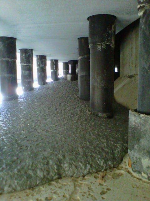
The grout layer seen from underneath the tower base flange. The anchor bolts pass through the flange, and the grout fills the entire space between the steel and the concrete pedestal. This thin layer must transfer compressive loads of several thousand kilonewtons without any voids or discontinuities.
The materials
The wind energy industry has converged on a small number of high-performance cementitious grout products specifically developed and qualified for the tower-foundation interface. These are not ordinary construction grouts — they are engineered products with tightly controlled mix designs, and the turbine manufacturers typically maintain approved product lists that specify exactly which grouts may be used.
Years ago I worked with the MasterFlow 9200 from BASF. It is a pre-blended, cement-based, non-shrink grout supplied in 25 kg bags. The bags contain a precisely proportioned mix of cement, graded aggregates, and proprietary additives — the contractor on site only adds water. This eliminates the risk of batching errors that would occur with site-mixed grouts.
It has a compressive strength exceeding 80 MPa at 28 days (and typically reaching 50 to 60 MPa within 24 hours at 20°C), a flexural strength of approximately 10 MPa, and very low shrinkage. The water-to-powder ratio is strictly controlled — the manufacturer specifies 2.25 litres of water per 25 kg bag at 20°C, and this ratio must be adjusted within narrow limits depending on ambient temperature. Too much water weakens the grout and increases shrinkage. Too little makes it impossible to pump and creates voids.
Other products used in the industry include for instance the Pagel V1/160 (common in German and northern European projects) and the FOSROC Conbextra range (used in some markets, particularly in southern Europe and Latin America). The FOSROC products are similar in concept — pre-blended, high-strength, non-shrink cementitious grouts — and the selection between brands is typically driven by the turbine manufacturer’s approved list and local availability.
There is also a specialist grouting company ecosystem. Firms like Exa Grout and similar contractors operate across wind markets as licensed grouting specialists, trained and certified by both the grout manufacturers and the turbine OEMs. This reflects the critical nature of the operation — many developers and EPC contractors prefer to subcontract grouting to a specialist rather than have the general civil works contractor perform it, because the risk of a poorly executed grout job is disproportionately high relative to its modest cost.
The process — step by step
Grouting in hot countries is often performed at night. This is not for dramatic effect — there are practical reasons. The grout is temperature-sensitive: the ideal application window is between 5°C and 30°C, with the optimal range around 10°C to 20°C. In warm climates (southern Spain, Morocco, Mexico, etc.), daytime temperatures during the construction season can easily exceed 35°C, which accelerates the setting reaction to the point where the grout may begin to harden before it has fully flowed under the flange. At night, temperatures drop into the acceptable range. Additionally, direct sunlight on the foundation and tower surfaces can create temperature differentials that affect curing.
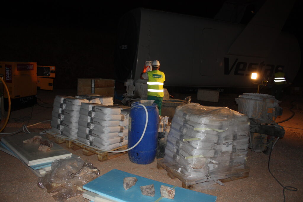
A night grouting operation. Pallets of pre-blended grout bags are staged at the tower base alongside the mixing equipment and diesel generator. The work is typically done at night to avoid high daytime temperatures that would accelerate setting and reduce the working time of the grout.
The process follows a strict sequence.
The first step is surface preparation. The top of the concrete pedestal must be roughened (to a minimum roughness of approximately 5 mm amplitude) to provide mechanical interlock with the grout. It must be clean — free of dust, oil, curing compound residue, and laitance (the weak surface layer that forms on concrete). And it must be moistened to a “saturated surface dry” condition: wet enough that the concrete will not absorb water from the fresh grout (which would cause premature drying and cracking), but without puddles of standing water that would dilute the grout locally.
The second step is formwork installation. A ring of temporary formwork is placed around the base of the tower, enclosing the gap between the flange and the pedestal. This formwork is typically made from closed-cell foam (blue or white polystyrene boards), sealed to the concrete and the steel with mastic or foam sealant. The formwork must be watertight enough to contain the fluid grout, with openings left at specific points for the injection hose and for air vents. The grouting is performed from one side, and the grout must flow around the entire circumference — typically 4 to 5 metres in diameter — pushing air out through vents on the opposite side.
The third step is mixing. The grout is mixed in a high-shear colloidal mixer — not an ordinary concrete mixer — to ensure complete dispersion of the cementitious particles. The water is measured precisely with a graduated container (not estimated), and the mixing time is controlled by chronograph: typically 7 minutes per batch at 20°C. Each batch uses a fixed number of bags (usually 4 to 6 bags, depending on the mixer capacity), and the batches must be mixed and pumped continuously, one after another, to avoid cold joints in the grout layer.
The fourth step is pumping. The mixed grout is pumped through a hose (typically 50 mm diameter) into the gap between the flange and the pedestal, starting from the injection point and flowing circumferentially in one direction. The grout is pumped continuously until it appears at the vent openings on the far side, confirming that it has filled the entire gap without leaving trapped air. The pump operator must maintain a steady flow rate — too fast creates turbulence and entrains air, too slow allows the grout to begin setting before the gap is fully filled. The typical flow rate specified by manufacturers is around 20 litres per minute per 75 kg of mixed grout.
The entire pumping operation, from the first bag mixed to the last vent sealed, must be completed within the grout’s working time — typically 45 to 60 minutes at 20°C. This means the operation is a carefully choreographed sequence: while one batch is being pumped, the next batch is already being mixed, and the bags for the batch after that are already being opened and staged. A grouting crew typically consists of 4 to 6 people: mixer operator, pump operator, formwork monitor, and helpers staging materials.
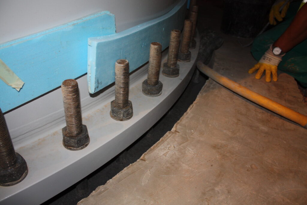
The grout layer immediately after pumping, with the blue foam formwork still in place. The grout has flowed around the anchor bolts and filled the gap between the tower flange (top) and the concrete pedestal. The smooth, uniform surface with no visible voids indicates a successful pour.
Quality control
The QC requirements for grouting are unusually detailed for a construction operation of this size, reflecting the critical nature of the joint. A typical grouting inspection includes over twenty inspection points, each requiring a sign-off before proceeding.
Before grouting, the inspector verifies: surface roughness and cleanliness (visual), concrete moisture condition (visual — no puddles), ambient temperature (measured with a thermometer, must be between 5°C and 30°C), concrete surface temperature (contact thermometer, same range), grout thickness (measured with a flexometer — the gap between flange and pedestal must be between 30 and 200 mm), product identification (visual — correct product, correct batch, not expired), and formwork integrity (visual — sealed, with vents correctly positioned).
During grouting, the inspector monitors: water dosage (graduated container — must match the manufacturer’s specification for the measured temperature), mixing time (chronograph — typically 7 minutes per batch), working time (chronograph — total pumping must complete within the allowed window), flow rate (chronograph — time per batch), and hose replacement during pumping (visual — must not introduce air into the grout line).

A spread flow test performed on site during grouting. The grout is poured into a standard cone, the cone is lifted, and the resulting spread diameter is measured. This test verifies that the grout has the correct consistency — too thick and it won’t flow under the flange; too thin and it may segregate or shrink excessively.
The most important on-site test is the spread flow test (sometimes called the “flow cone” or “slump flow” test). A sample of each batch is poured into a standardised cone on a flat plate. The cone is lifted, and the grout spreads under its own weight. The diameter of the resulting circle is measured and must fall within the range specified by the manufacturer. This test is a quick, reliable indicator of whether the water ratio is correct: too much water gives an excessive spread, too little gives an insufficient spread.
Additionally, cube or prism moulds are filled with grout from each batch for subsequent compression testing. Three moulds are standard per batch, and they are cured under conditions representative of the actual installation (not in a laboratory at controlled temperature — on site, next to the foundation). The moulds are tested at 24 hours, 7 days, and 28 days to verify that the grout achieves the specified compressive strength.
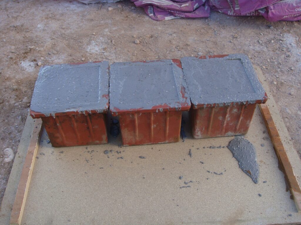
Cube moulds filled with grout from the on-site batches. These will be tested for compressive strength at 24 hours, 7 days, and 28 days. The results must meet the minimum specified by the turbine manufacturer — typically 50 MPa at 24 hours and 80 MPa at 28 days.
After grouting, the formwork is left in place for at least 24 hours before removal. The exposed grout surfaces are inspected for cracks, voids, and segregation. Any visible defect must be documented and assessed — small surface cracks may be acceptable, but voids or incomplete filling require remediation, which can range from local patching to a complete re-grout (an expensive and disruptive operation that involves chipping out the failed grout and starting over).
The temperature challenge
Temperature is the single most critical environmental factor in grouting. The compressive strength development of cementitious grout is strongly dependent on the curing temperature, and the relationship is not linear.
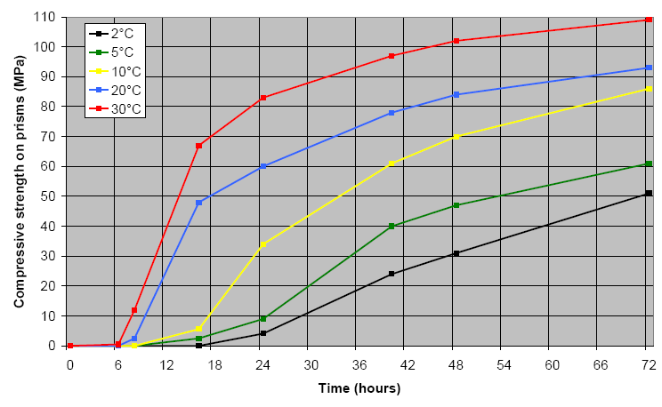
Compressive strength development of MasterFlow 9200 at different curing temperatures. At 30°C, the grout reaches 60 MPa in 18 hours. At 5°C, it barely reaches 10 MPa in the same period. At 2°C, strength development essentially stalls for the first 24 hours. This chart explains why grouting timing and temperature management are so critical.
At 30°C, the grout reaches approximately 60 MPa within 18 hours — comfortably above most minimum requirements. But at 5°C, the same grout reaches barely 10 MPa in 18 hours and takes over 72 hours to reach 60 MPa. At 2°C, strength development is almost negligible for the first 24 hours.
This has direct operational consequences. In cold-climate projects (Scandinavia, Patagonia, highland sites in Turkey or Morocco), grouting may need to be delayed until temperatures rise above the 5°C minimum, or the foundation and grout must be heated with thermal blankets and hot-air blowers — adding cost and complexity. In hot-climate projects, the challenge is the opposite: the grout’s working time shortens dramatically, and the crew must work faster and with smaller batches to avoid the grout setting in the mixer or the pump hose.
The water ratio also varies with temperature. At higher temperatures, more water can be added (within strict limits) to compensate for faster evaporation and maintain workability. At lower temperatures, less water is used. The manufacturer’s application guide provides a temperature-dependent dosage table that the site team must follow precisely.
Common failure modes
When grout problems occur, they typically fall into a few categories.
Voids are the most common issue. Air pockets trapped under the flange — usually because the grouting was done too fast, the formwork had leaks that broke the grout’s hydraulic head, or the vents were positioned incorrectly — create zones where the load is not transferred. If the voids are small and localised, they may be tolerable. If they are extensive, they create uneven loading on the anchor bolts and can lead to bolt fatigue failures.
Shrinkage cracking occurs when the water ratio is too high or the curing conditions are poor (hot, dry, windy weather that causes rapid moisture loss from the exposed grout surfaces). The cracks themselves are not necessarily structural, but they allow water ingress, which leads to freeze-thaw damage in cold climates and corrosion of the anchor bolts over time.
Segregation happens when the grout separates into its constituent phases during placement — the water rises to the top and the aggregates settle to the bottom. This produces a weak, porous layer at the top of the grout (directly under the flange, where it matters most) and a dense, aggregate-rich layer at the bottom. Segregation is almost always caused by excessive water or insufficient mixing.
Incomplete curing occurs when the grout is placed at temperatures below the minimum and no protective measures are taken. The grout may appear to have set, but its strength is far below the specified value. If the tower is loaded before the grout has reached adequate strength, the grout can crush and displace under the concentrated bolt loads.
All of these failure modes are preventable with proper execution of the procedures described above. The grouting operation is not technically difficult — it is a matter of discipline, attention to detail, and respect for the manufacturer’s specifications. The crews that do it every day, foundation after foundation, rarely have problems. The problems tend to occur when an inexperienced crew attempts the work for the first time, or when schedule pressure leads to shortcuts — grouting at temperatures outside the allowed range, estimating the water ratio instead of measuring it, or skipping the spread flow test.
What it costs
The direct cost of grouting a single turbine foundation is modest in the context of a wind farm project: typically 2,000 to 5,000 euros, including materials (grout bags, consumables), equipment (mixer, pump, generator), and labour. For a 50-turbine wind farm, the total grouting cost is in the range of 100,000 to 250,000 euros — roughly 0.1% to 0.2% of the total project cost.
The cost of a grouting failure, however, is orders of magnitude higher. Remediation of a failed grout joint requires mobilising a crane to unload the tower (or at minimum, to remove sufficient bolt tension to allow grout removal), chipping out the old grout without damaging the anchor bolts, and re-grouting. Depending on the extent of the failure and the accessibility of the site, the remediation cost can range from 20,000 to 100,000 euros per turbine, plus lost production during the downtime. If multiple foundations are affected (because the same crew made the same mistake across the site), the total cost can reach into the millions.
This asymmetry — low cost of doing it right, very high cost of doing it wrong — is why the industry has moved toward specialist grouting contractors and why the quality control requirements are so detailed. It is one of the few construction operations in a wind farm where spending an extra few hundred euros on a qualified crew and proper QC can save a hundred times that in avoided repairs.
Key takeaways
Grouting the tower-foundation interface is a small operation with outsized consequences. The grout layer is thin, the material cost is low, and the work takes a few hours — but it is the only path through which the entire weight and dynamic loading of the turbine reaches the foundation.
The recipe for success is straightforward: use the correct product from the turbine manufacturer’s approved list, follow the manufacturer’s application guide to the letter (especially on water ratio and temperature limits), employ a trained crew that has done it before, perform all the specified QC checks (surface preparation, temperature, spread flow, cube samples), and do not accept schedule pressure as a reason to skip any of these steps.
The recipe for failure is equally straightforward: use an unqualified crew, grout outside the temperature window, estimate instead of measure, and skip the tests. The consequences will not be visible on the day of grouting — they will appear months or years later, as cracking, water ingress, and bolt corrosion gradually undermine the most critical interface in the entire turbine structure.
Based on project experience across multiple wind farms in Spain, Morocco, Turkey, and Latin America, the BASF MasterFlow 9200 Application Guide and associated quality control documentation.
Leave a Reply