Reading the wind farm BoP related info of several companies in the sector, such as Gamesa, Vestas and Nordex, I’ve found a variety of proposed shapes and dimension for the crane pads.
Basically a rectangular solution looks like the more reasonable option, but sometimes triangular, polygonal and even circular pads are found. I think that they waste space and that they can be complicated to construct.
The easiest solution is to align the pad to the access road: doing so it is possible to use the access road to assembly the boom of the main crane (if it was disassembled when moved from a position to the other).
The standard size for blades of 45 meters would be around 40×45 meters: this is a “Full Storage” solution, because it allows storing blades, tower, nacelle and all the materials in the platform.
Other solution are used in mountainous wind farms where earthwork is expensive: in this case a temporary storage area is made somewhere nearby on a flat zone, but this solution is more expensive and time consuming, because it needs more trucks movements and several loading/unloading with the auxiliary cranes.
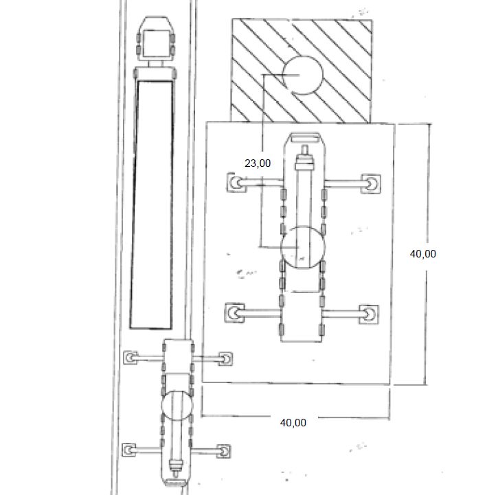
The biggest problem is how to allow to the trucks to turn around: for instance, in the Gamesa manual for BoP no clear solution is given to this problem (attached picture).
I normally study this problem on a case by case basis simulating the truck movements with AutoTURN, as no general solution can be provided.
Another solution I use every now and then is to split the storage area: blades on one side of the road, and tower elements on the other. It can be useful when, to minimize earthworks, a 2 level crane pad is realized.
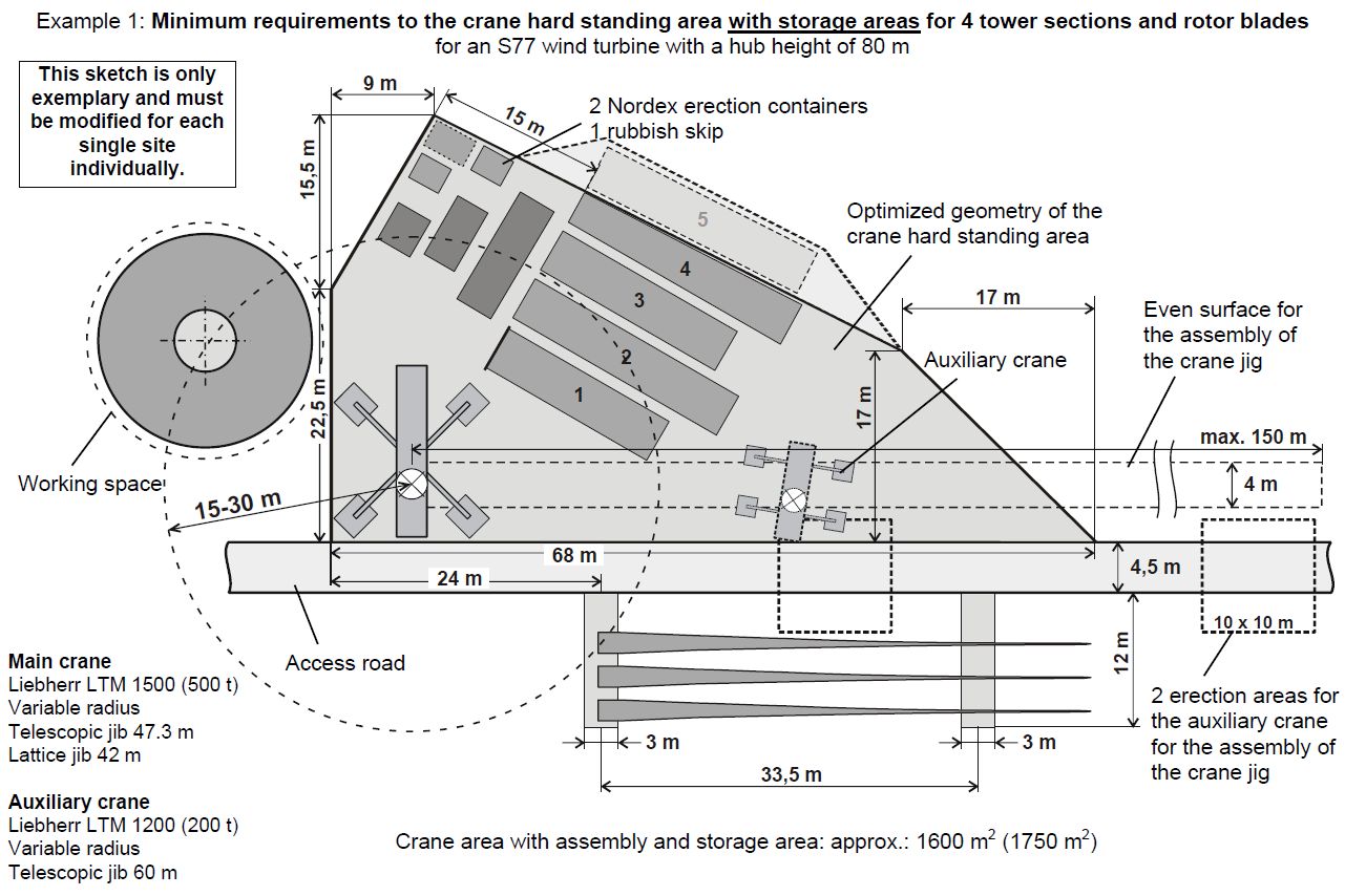
Below as an example you can see Gamesa and Nordex solution.

Leave a Reply