Category: Roads
-
Wind farm internal roads optimization
In parallel with the optimization of crane pads (you can find the article on the topic here) I am also trying to automate the calculation of wind farm internal roads. At the moment I have developed three solutions: the first joins the turbines looking for the minimum spanning tree (MST), i.e., the shortest possible connection….
-
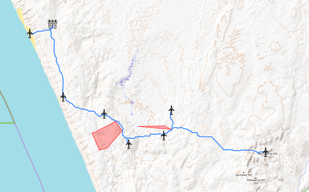
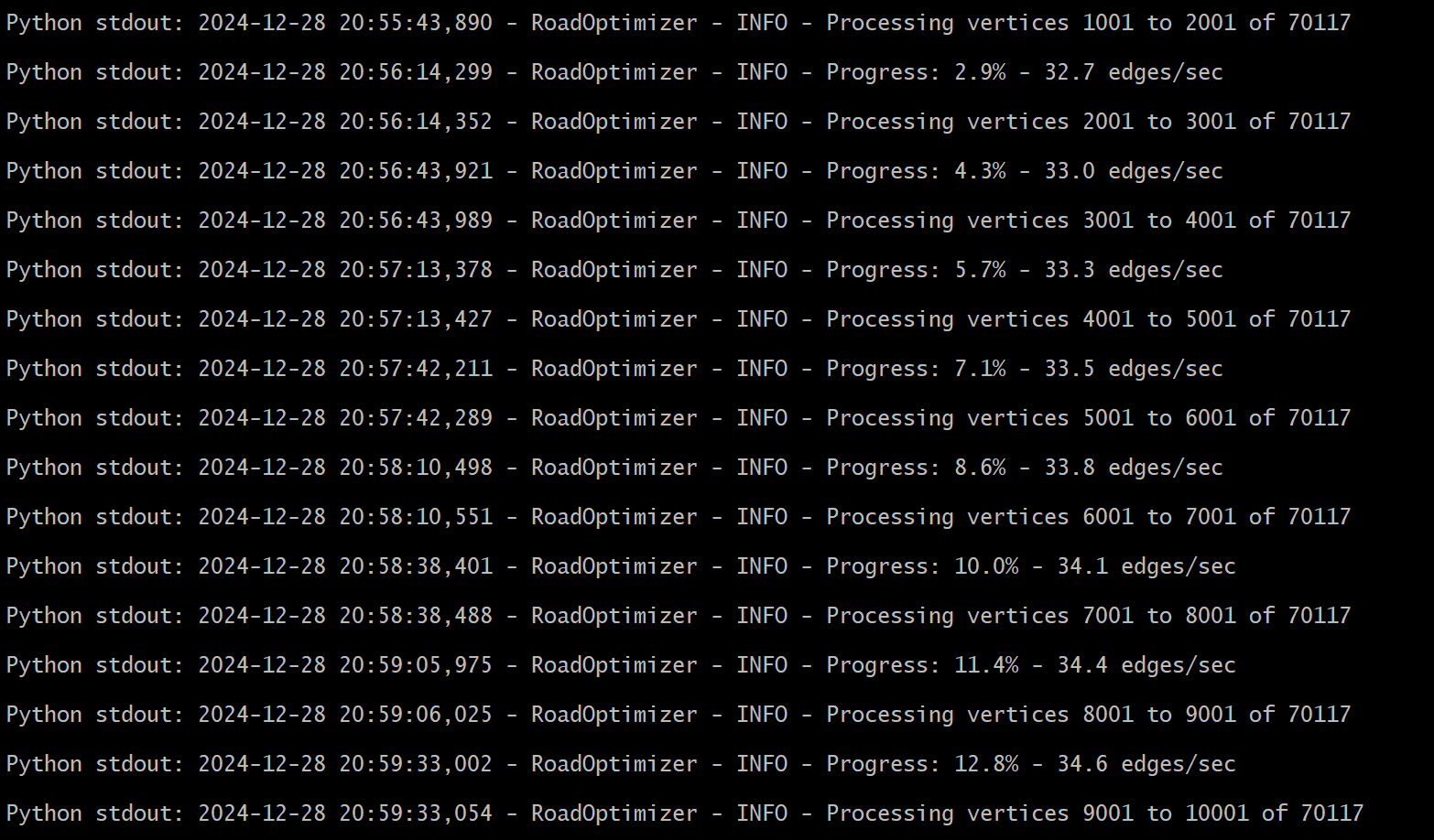
Internal roads optimization: an update
These vacation days I am managing to find time to work on my “automatic wind farm optimization” project.Yesterday I managed to add a new feature to the optimization of wind farm internal roads.In the new version, the algorithm is also able to consider existing roads and “no-go-areas” (areas that cannot be used due to environmental…
-
Wind farms road stabilization with polymers
Road stabilization with polymers is a method used to enhance the performance and longevity of roads. It basically consist in the incorporation of polymer materials during the construction or maintenance of roads to improve their mechanical properties, reduce maintenance needs, and increase the road resistance to environmental factors. “Polymer” is a very broad term. A…
-
Road Design & Earthwork Optimization Software for Wind Farm Networks
I have been contacted by Erin Wasney, Business Development Manager at Softree Technical Systems. She proposed to write a guest post on RoadEng, a software developed to design long roads and large networks of low volume roads faster and easier than other civil design software. I am more than happy to share his post with…
-
Infraworks for due diligence and preliminary designs
If you either work for a WTG manufacturer or any electric utility the situation in which you are asked to do a complete analyse of a project very quickly (like in 2 or 3 days) is very common. You are usually asked to do this task for several reasons: Preparation of a first rough layout…
-
Modifications to wind farm access roads: a step-by-step guide
One of the problems that occurs frequently to engineers working on wind farms is how to modify existing access roads to allow the transit of special vehicles. I was contacted by several readers of the blog who had this issue – the last one was Egil from Norway who led me to write this article….
-
Plate bearing test for wind farm roads & hardstands
Plate bearing test (also known as “plate load”) is one of the in situ investigations most frequently used during the construction of wind farms. Its objective is to confirm that roads and hardstands meet the minimum requirements for compaction and bearing capacity. Basically, it is performed pushing a steel plate against the material to be…
-
Technical requirements and tests for wind farm roads and hardstands
Two readers asked me how to assess the quality of the civil works in a wind farm. This is a very broad topic and it requires some previous knowledge in geotechnics and road construction. However, I think that someone might found useful an introductory article with some of the requirements that I would recommend to…
-
Wind farms Road Survey: 3 things you should ask
One of the first point that I try to spot when I receive an offer for a wind farm is an unusual dispersion in prices among subcontractors. Usually, it means that there has been a misunderstanding regarding the actual scope of works. Several items have usually very stable, predictable prices. This is the case for…
-
Slopes stabilization using Vetiver
I’ve recently worked on a slope stabilization preliminary project. Among other action, the use of Vetiver grass for stabilization purposes has been suggested by the customer, who had used it successfully in another wind farm in the same area. Although this technique is used in Italy and other European country I was not an expert,…