Category: Crane pads
-
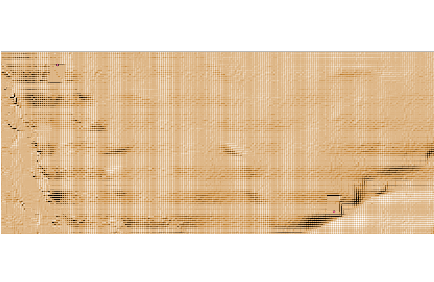
Wind farm crane pads optimization: a solution with QGIS
QGIS is a great open source GIS software that I often use to display information in various formats (e.g. SHP). It has an interesting number of additional plug-ins that enhance its capabilities. Over this Christmas break I managed to find a few hours and have virtually finished developing a plug in that helps define the…
-
Crane hardstands for installation of wind turbines: a handbook
Due to the pandemic this year we have been forced to go on vacation by car – the majority of flights from Germany to southern Italy have been cancelled, so we are making a 2000+ Km car trip with our three kids. While my wife was driving I searched something to read and I have…
-
Plate bearing test for wind farm roads & hardstands
Plate bearing test (also known as “plate load”) is one of the in situ investigations most frequently used during the construction of wind farms. Its objective is to confirm that roads and hardstands meet the minimum requirements for compaction and bearing capacity. Basically, it is performed pushing a steel plate against the material to be…
-
Technical requirements and tests for wind farm roads and hardstands
Two readers asked me how to assess the quality of the civil works in a wind farm. This is a very broad topic and it requires some previous knowledge in geotechnics and road construction. However, I think that someone might found useful an introductory article with some of the requirements that I would recommend to…
-
Wind farms roads and crane pads made of laterite
I’m currently having the pleasure of working at a wind farm project in Senegal. One of the challenges I’m facing is the use of unconventional materials, at least based on my European background. For instance, the internal roads and crane pads will be probably made of laterite, a solution very common in tropical climates successfully…
-
Wind farm civil works projects: typical errors
Here you have my collection of errors I frequently see when I check wind farm project developed by external companies. Being a quite peculiar sector is no surprise that I normally found several mistakes: here you have the most commons. Error #1: two levels crane pad / foundation area designed without considering the slopes…
-
Crane pads shape and dimension
Reading the wind farm BoP related info of several companies in the sector, such as Gamesa, Vestas and Nordex, I’ve found a variety of proposed shapes and dimension for the crane pads. Basically a rectangular solution looks like the more reasonable option, but sometimes triangular, polygonal and even circular pads are found. I think that…