
How to choose the right busbar arrangement for your wind farm?
Every onshore wind farm needs a grid connection substation, either an existing or a brand new one. And if you need to build a substation for your wind farm, one of the very first design decisions you’ll face — one that shapes the entire layout, the budget, and the long-term operational flexibility — is the busbar configuration.
Should you go with a single busbar or a double busbar?
This post walks you through both options. As a disclaimer, remember that I am a Civil Engineer, so electrons are not my main strenght.
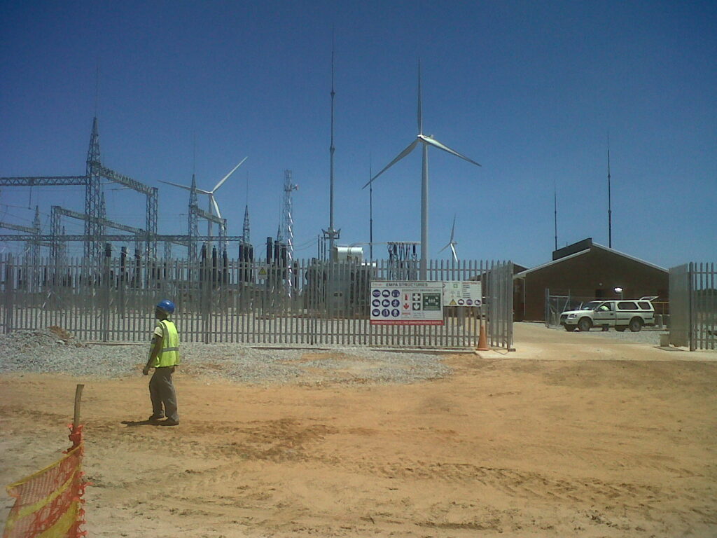
A completed 110kV AIS substation at a wind farm in South Africa. Note the steel gantry structures and the power transformer (right)
What is a busbar?
A busbar is the common electrical node that connects all the bays (line bays, transformer bays, bus-coupler bays) within the substation switchyard. In an Air Insulated Substation (AIS), busbars are typically aluminium or copper conductors supported by post insulators on steel gantry structures.
The busbar configuration determines:
- How many busbars run through the switchyard
- How equipment is connected to those busbars
- What happens during maintenance — can you isolate one section without losing the entire substation?
- The physical size of the switchyard
Single Busbar Configuration
In a single busbar arrangement, all bays connect to one common busbar. This is the simplest and most compact configuration.
These are the key features of the single busbar SLD:
- One main busbar (BUS 1) running across all bays
- A bus-section circuit breaker dividing the busbar into two halves — this allows maintenance on one half while the other remains energised
- Two line bays connecting to the overhead transmission line
- Two transformer bays (one per power transformer)
- Each bay includes: line disconnector (DS), circuit breaker (CB), current transformers (CT), voltage transformers (VT), surge arresters (SA), and earthing switches (ES)
- Protection relays: distance protection (21/21N), overcurrent (50N/51N), transformer differential (87T), busbar zone (87BB)
Layout
The single busbar layout is compact. For a 110kV installation, typical bay width around 7.5 to 8 metres and a total switchyard width: depends on number of bays, but significantly narrower than double busbar.
This makes the single busbar the preferred choice when land is constrained, Budget is tight, the grid code does not require N-1 redundancy at the substation level and the wind farm has a single transformer (usually, small to medium projects).
Double Busbar Configuration
In a double busbar arrangement, two parallel busbars (BUS 1 and BUS 2) run through the switchyard, connected by a bus-coupler bay. Each feeder bay has two busbar disconnectors (BB1 DS and BB2 DS), allowing it to be connected to either busbar.
Key features of the double busbar SLD:
- Two main busbars (BUS 1 and BUS 2)
- A bus-coupler bay with its own circuit breaker, connecting the two busbars — during normal operation, the bus-coupler is closed and both busbars are energised in parallel
- Each feeder bay has two busbar disconnectors (BB1 DS and BB2 DS) to select which busbar it connects to
- Same protection philosophy as single busbar, but with added busbar protection zones
The bus-coupler is the heart of the double busbar scheme. It enables:
Transferring feeders from one busbar to the other without interruption, isolating one entire busbar for maintenance while keeping all feeders in service on the other busbar and splitting the busbars to separate generation sources (useful when the grid operator requires it).
Layout
The double busbar layout is significantly wider. A typical bay width can be between 10.5 and 12 metres. The two busbar bus-coupler bay add considerable depth to the substation.
| Parameter | Value |
|---|---|
| Phase-to-phase spacing (main busbars) | 1,750 mm |
| Phase-to-phase spacing (branch buses) | 2,000 mm |
| Main busbar levelling (TOG) | +5,500 mm |
| Jack bus levelling (TOG) | +4,100 mm |
| Outgoing line height | +8,300 mm |
| Total switchyard width | ~55,750 mm |
Power transformer with HV bushings, conservator tank, and cooling radiators. The gravel bed underneath provides fire protection and oil containment.
The Clearance Rules That Drive the Layout
The physical dimensions of an AIS substation are fundamentally driven by electrical clearance requirements. The reference standard is IEC 61936-1 (“Power installations exceeding 1 kV a.c.”).
The key principle: since air is the insulation medium, live conductors must be separated by sufficient distance to prevent flashover under the worst-case overvoltage (lightning impulse).
Minimum Air Clearances (N)
For a 110kV system (Um = 123kV), with rated lightning impulse withstand voltage of 550kV:
| Parameter | Formula | 110kV Value |
|---|---|---|
| Min P-P & P-E clearance (N) | From IEC 61936 table | 1,100 mm |
| Min ground clearance (H) | N + 2,250 mm | 3,350 mm |
| Min working clearance (D_V) | N + 1,000 mm (for Un <= 110kV) | 2,100 mm |
| Transport clearance (T) | N + 100 mm (min 500) | 1,200 mm |
| Min height at external fence (H’) | N + 4,500 mm (min 6,000) | 5,600 mm |
The correlation is approximately 2 mm per kV of lightning impulse withstand voltage — a useful rule of thumb for quick estimates.
Why These Numbers Matter
Ground clearance (H = 3,350 mm): determines the height of the steel gantry structures. All live parts must be at least 3.35m above ground where people can walk.
Working clearance (D_V = 2,100 mm): determines the spacing between the disconnector switch and its adjacent equipment. Maintenance workers need safe clearance from live parts.
Phase spacing: driven by the disconnector type. Centre-break disconnectors (the most common for 110kV) have rotating arms that define the minimum phase-to-phase distance.
External fence clearance (H’ = 5,600 mm): any live part visible from outside the substation fence must be at this minimum height — protecting the general public.
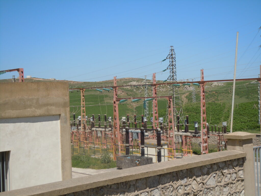
Current transformers (CTs) and voltage transformers (VTs) at the substation. These instrument transformers feed measurement data to the protection relays and metering systems.
Clearance Comparison Across Voltage Levels
For reference, here are the key clearances for common wind farm substation voltages:
| Parameter | 110kV | 132kV | 150kV | 220kV |
|---|---|---|---|---|
| Min clearance N (mm) | 1,100 | 1,300 | 1,500 | 2,100 |
| Ground clearance H (mm) | 3,350 | 3,550 | 3,750 | 4,350 |
| Working clearance D_V (mm) | 2,100 | 3,300 | 3,500 | 4,100 |
| Height at fence H’ (mm) | 5,600 | 5,800 | 6,000 | 6,600 |
| Bay width — single bus (m) | 7.5-8 | — | — | — |
| Bay width — double bus (m) | 10.5-12 | — | — | — |
Notice how the clearances increase substantially with voltage — a 220kV substation needs almost double the clearances of a 110kV one, which directly translates to larger (and more expensive) gantry structures and wider bay spacing.
Key Components in the Switchyard
Before choosing a configuration, it helps to understand what equipment sits in each bay. Here’s a quick reference of the main AIS components:
Power Transformer (TR): the main step-up transformer, typically 33/110kV (or 33/132kV, 33/150kV depending on the grid voltage). This is the single most expensive piece of equipment in the substation. Wind farm transformers are typically ONAN/ONAF cooled, with on-load tap changers (OLTC) for voltage regulation.
Circuit Breaker (CB): the protection workhorse. SF6-insulated for HV, vacuum for MV. Rated to interrupt fault currents up to 31.5kA or 40kA for 1 second. Each bay (line, transformer, bus-coupler) has its own CB.
Disconnectors (DS): these safety devices providing visual isolation — you can physically see that the circuit is open. They must only be operated with the CB open (no-load switching). Types include centre-break, double-break, knee-type, and pantograph. The disconnector type is the dominant factor in determining phase-to-phase spacing, because the rotating contact arms define the minimum clearance envelope.
Current Transformers (CT) and Voltage Transformers (VT): Instrument transformers that scale down the primary current and voltage to levels suitable for protection relays and metering equipment. CTs are typically 800-1600/1A; VTs are 110kV/110V.
Surge Arresters (SA): Metal-oxide devices that clamp overvoltage transients from lightning strikes or switching operations. Installed on each line entry and at transformer terminals.
Earthing Switches (ES): these are safety devices that connect isolated sections to ground, protecting maintenance personnel from residual voltages or induced currents.
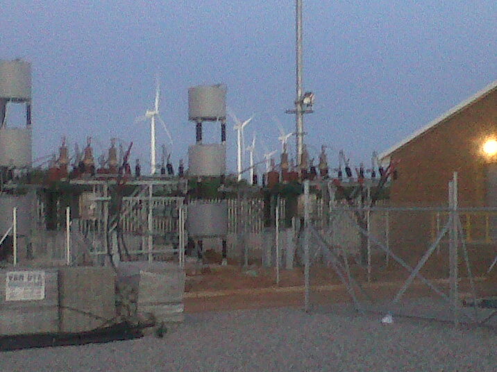
Equipment overview: CTs, VTs, and surge arresters mounted on their support structures, with wind turbines visible in the background.
Single vs Double Busbar: The Decision Matrix
Here’s the practical comparison that matters for wind farm projects:
| Criterion | Single Busbar | Double Busbar |
|---|---|---|
| Land footprint | Smaller (bay width 7.5-8m) | Larger (bay width 10.5-12m) |
| Capital cost | Lower — less equipment, less steel, less civil works | Higher — additional busbar, bus-coupler bay, extra disconnectors per bay |
| Maintenance flexibility | Limited — bus-section helps, but one half must be de-energised | Full — any bay can be maintained while all others remain in service |
| Reliability (N-1) | Partial — bus-section provides limited redundancy | Full N-1 — loss of one busbar does not affect the other |
| Complexity | Simple — fewer switching operations | More complex — requires switching procedures for busbar transfers |
| Typical application | Wind farms < 100MW, single transformer, relaxed grid code | Wind farms > 100MW, dual transformers, strict grid code (N-1 requirement) |
| Construction time | Shorter | Longer |
When to Choose Single Busbar
Small to medium wind farms, where the grid code does not requirw redundancy at the substation. Only one power transformer is needed, and/or budget and schedule are priorities. A bus-section (splitting the single busbar into two halves with a CB) provides sufficient operational flexibility
When to Choose Double Busbar
Large wind farms with two or more transformers, if the grid code or the TSO (Transmission System Operator) explicitly requires N-1 redundancy or if the project has multiple generation feeders that the TSO wants to control independently,
Long-term operational flexibility often justifies the additional investment
Additionally, in some situations the substation is shared with other generation plants or is part of a bigger collector substation.
Gantry portal for overhead line entry at a wind farm substation in Morocco. The line tension and sag requirements determine the gantry height and structure.
Design Input Parameters
When starting a substation layout design, you need the following input data:
- Busbar configuration — single (with/without bus-section) or double (with/without bus-coupler)
- Number of bays — how many line bays, transformer bays, capacitor bank bays?
- Highest voltage of installation (Um) — e.g. 123kV for a 110kV system
- Rated lightning impulse withstand (BIL) — e.g. 550kV for 123kV systems
- Maximum fault level — e.g. 31.5kA for 1 second (from the grid operator)
- Disconnector type — centre-break is the most common for 110kV; this drives phase spacing
- Coordinates of the last transmission tower — the overhead line entry point constrains the switchyard orientation
- Local regulations — snow loading (increases ground clearances), seismic requirements, environmental restrictions
The MV Side: Collector Switchgear
While this article focuses on the HV switchyard, it’s worth noting that the MV collector switchgears (typically 33kV) sits inside the substation building. This is where all the underground collector cables from the individual wind turbines terminate.
An MV switchgear is typically gas-insulated (GIS) and arranged in a ring-main or radial configuration with multiple feeder panels. Each panel includes a vacuum circuit breaker, CTs, and protection relays.
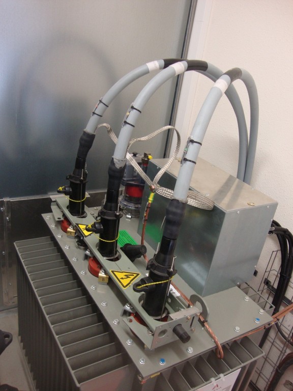
Interior of an MV switching centre showing cable terminations and switchgear. The three-phase cable heads connect the underground collector cables to the MV busbar inside the enclosure.
Key Takeaways
- The busbar configuration is a project-level decision driven by the grid code, the number of transformers, and the required reliability. Don’t over-engineer — a single busbar with bus-section is perfectly adequate for most wind farm substations.
- Clearances drive dimensions. Everything in the layout traces back to IEC 61936 clearance tables. Learn the formula: minimum clearance N is approximately 2 mm per kV of BIL.
- The disconnector type determines phase spacing. Centre-break disconnectors are standard for 110kV, but always verify the Pmin from the specific manufacturer’s datasheet.
- Double busbar costs more but gives flexibility. The additional cost is not just the extra busbar — it’s wider bays (more steel, more civil works, more land), a bus-coupler bay, and two busbar disconnectors per feeder bay instead of one.
- Always check the grid code first. Some TSOs (like REE in Spain or TERNA in Italy) have specific requirements for busbar configuration that override any cost optimisation.
References
- IEC 61936-1: Power installations exceeding 1 kV a.c. — Part 1: Common rules
- DNV GL Memo GL01/14.10.31: HV Air Insulated Substation (AIS) layout guidelines
Leave a Reply